Nice one mate, the sketch looks good
From a rough check of the maths it seems OK
A few things you'll need to work through if this is an actual design though
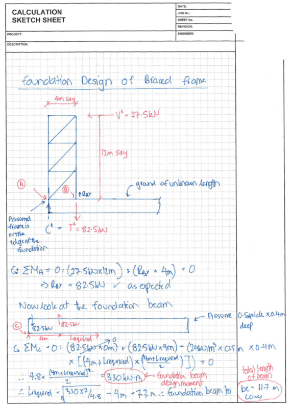
1) You've only got a 0.35m deep beam but your design moment is 82.5kN * 1.2m = 99kN.m - you may struggle to get that to work efficiently
Perhaps going to a 500mm wide beam that's 500mm deep could be more efficient? Play around with those options - I don't know what your constraints are so I can't help you there
2) As I mentioned in my previous post, I assumed that we were summing moments around the very edge of the footing, which you have now emulated
In reality, the compression isn't ultimately resisted by the concrete, it's resisted by the much softer and weaker soil underneath the concrete
So the compression block in the soil is what matters
Do you have geotechnical parameters for your soil bearing capacity etc? You'll need to account for this as it will reduce your lever arm and mean you need a bigger footing than currently sized
As a quick hint, I've chucked your footing into my spreadsheet I use for these designs and it doesn't work when accounting for this effect
")
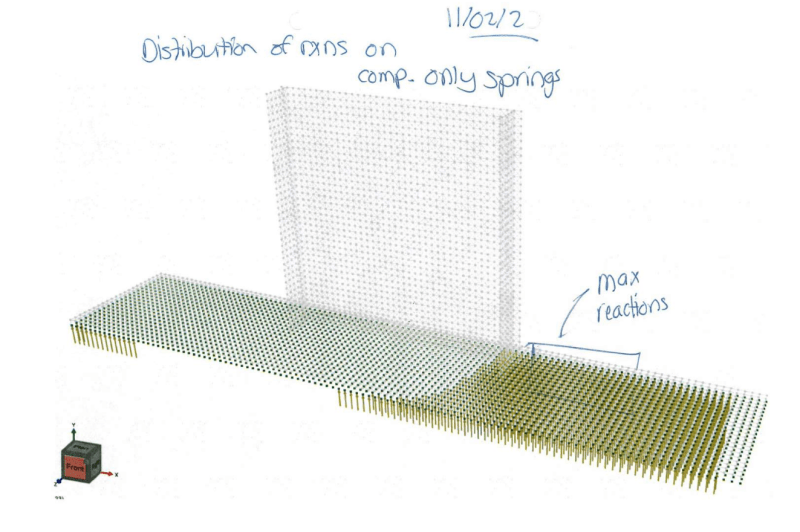
As a visual example that may help, the below is a flanged wall I designed over a large footing
I modelled it up on springs to represent the soil and this is an output showing the force reactions that occur
You can see where all the greeny arrows are that there is compression reaction - makes sense as it's near the end of the wall
Then there is a large area with no reaction - this is where the concrete is actually uplifting so the soil doesn't support it
Eventually, near the left side, enough concrete has been picked up that the footing is no longer in net uplift
The key lesson here being: something may be stable for overturning but that doesn't mean it hasn't actually lifted off the ground!
You commonly here about this in footing design as "the middle third rule" or "the b/6 rule" which considers where the soil reaction is and whether any uplift is required for stability
3) Just to make it clear - the connection of the tension leg to the concrete does need to handle the 82.5kN load (plus whatever shear is on it!) so make sure you do design for that force
4) Just to add to the piles of things to consider...in this example we have assumed that there is no significant GLOBAL axial demand on the frame
If this frame was say a fixed base portal frame leg instead, then we would have a global tension/compression (from frame action) and a moment at the portal base (from fixed base action)
In this case you need to consider both the moment and the tension/compression when doing your freebody / sum of moments on the footing
One of the effects you will identify with that is that an asymmetric system can become directionally critical i.e. you get different footing designs if your loading is -> vs <-
No stress about that misunderstanding, it's all part of the learning process!
Funnily enough I went through this exact type of problem with one of the guys in the office a few months ago
He thought he needed 50kN (2m x 1m x 1m!) of concrete under his portals
We modelled up a few ground beams to represent the as-drawn structure, and turns out everything resolves nicely without needing any extra concrete at all - just a few more bars
I distinctly recall two separate conversations that taught me the principles I've just shared with you, so we've all been there
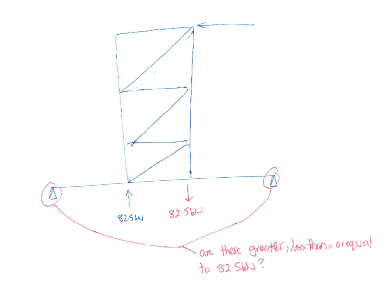
If you want the super easy way to conceptualise the problem, think about the below - you can inherently see that an uplift of 82.5kN under the leg doesn't mean we need 82.5kN of concrete - just that the moments need to resolve