Continue to Site

Eng-Tips is the largest engineering community on the Internet

Intelligent Work Forums for Engineering Professionals

  • Congratulations waross on being selected by the Eng-Tips community for having the most helpful posts in the forums last week. Way to Go!

COLUMN DESIGN

Status
Not open for further replies.

gotlboys

Civil/Environmental
May 31, 2015
61
In interior column design, should we consider moments from the beams (four sides) as we do for corner columns (biaxial bending) or interior columns are only subjected to axial reactions from beams?
How do we differentiate the load transfer of interior columns to exteriors as they commonly support only three beams; two being collinear and the other is perpendicular to the two?
Any reference showing the analysis of such load transfer will be a great help.
 
Replies continue below

Recommended for you

Unless they are a part of a moment frame, just axial.

Mike McCann, PE, SE (WA)


Apologize for missing that important point, it is a four-story building located in moderate seismic region. Basically they are part of the MRF.
Thank you so much for giving some insight on that.
I am new to actual structural design.
 
If the columns are part of a moment resisting frame, of course they have to be designed for moments. And if this is a reinforced concrete frame, there are code requirements to design for moment interactions due to gravity loads.
 
Mr. Hokei, I have the reference which is ACI 318 to be followed for deigning of such concrete members. My confusion lies on the forces that would come down to the supporting column considering their location as I have mentioned above.
 
The building codes we typically use require alternating live loads.

So even with interior columns, you would have situations where alternative (odd, even, adjacent) bays are loaded, causing bending moments in those interior columns.
So it isn't just axial. ASCE 7 requires this along with other codes.

As far as references to help you understand the analysis of such frames I can't help you much. The analysis we would use would simply involve a 3D frame model using
a structural program (RISA, RAM, ROBOT, etc.) and separate the floor live loads into different cases so you can apply live loads in various patterns.

I have typically alternated about 75% of the total live loads on floors (i.e. 25%LL is uniform and constant).


Check out Eng-Tips Forum's Policies here:
faq731-376
 
Mr. Jae, thank you so much for that information especially your own way of getting maximum moment with alternating load patterns. As I tried to figure out what you explained, my understanding is that the "moment on interior column" is basically caused by live loads, while dead load moments are cancelled out assuming UDL.
I am only using staad pro to cross-check my spreadsheet for finding moments and reactions on continuous beams and 2D frames. I am going to practice making some simple 3D to see the results.
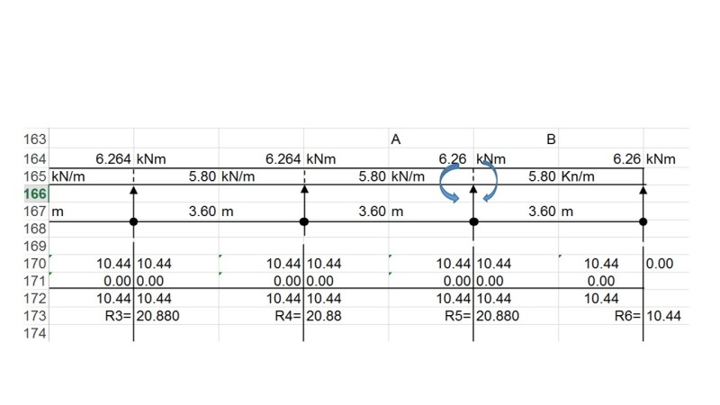
Attached pic is my spreadsheet I am used to getting moments and reactions. I purposely put two bending moment signs which indicate that the bending moments from Beam A and B at the support (column) cancel out each other. So, my assumption has usually been "no dead load moment transferred to interior supports".
I am more than happy to be corrected on this particular analysis.

moment_ofcxxy.jpg
 
my understanding is that the "moment on interior column" is basically caused by live loads, while dead load moments are cancelled out assuming UDL.
Well - sometimes there are dead load moments on interior columns due to differences in spans on either side - if you have uniform bays then the dead load moments would be closer to, or equal to, zero - assuming that all your stiffnesses (beams and columns) are very symmetrical.

For 3D model applications - it seems to me that the code is somewhat silent on how to "alternate" the live loads - do the patterns run in strips across the building or do you use a checkerboard pattern?

For one-way continuous beam designs the correct patterns to use are:
Odd Spans only
Even Spans only
Adjacent spans (1) - i.e. spans 1, 2, 3, 5, 6, 8, etc.
Adjacent spans (2) - i.e. spans 2, 3, 5, 7, 8, 10, etc.
Adjacent spans (3) - i.e. spans 1, 3, 4, 6, 8, 9, etc.
Full uniform live load

The odd and even span arrangements get you the maximum positive moments
The adjacent span arrangements get you the maximum negative moments.
The full uniform and some of the adjacent arragements get you the maximum shears.

How you take the above arrangements and convert to a 3D bay system takes some thinking and experimenting.


Check out Eng-Tips Forum's Policies here:
faq731-376
 
Mr. Jae, I am more comfortable with strip method directly on the beam.
I am from Timor-Leste where English design books are not available. I finished my study in the Philippines and have returned home a year ago. Luckily few E-books are available with limited pages though.
I appreciate very much on the insight you share to help me doing a bit better than yesterday.
 
Status
Not open for further replies.

Part and Inventory Search

Sponsor