Continue to Site

Eng-Tips is the largest engineering community on the Internet

Intelligent Work Forums for Engineering Professionals

  • Congratulations The Obturator on being selected by the Eng-Tips community for having the most helpful posts in the forums last week. Way to Go!

Cm coefficient calculation for B1 multiplier

Status
Not open for further replies.

BAGW

Structural
Jul 15, 2015
392
Hi,

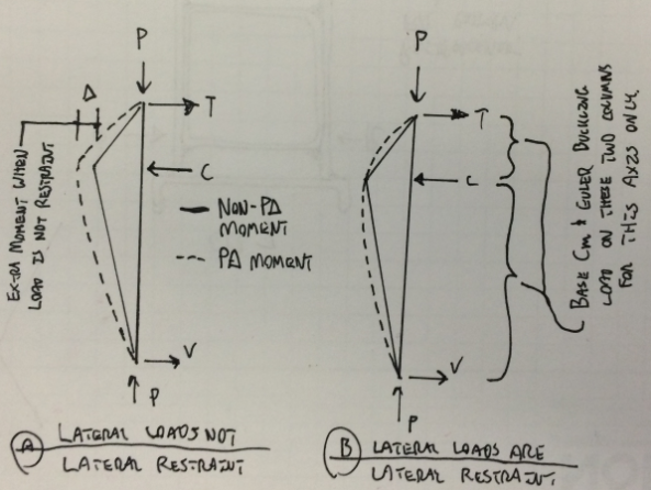
According to Appendix 8, cm = 1.0 when columns are subjected to transverse loading between supports. What is this transverse loading? What causes transverse loads? Is this from lateral loads (wind/seismic)?
 
Replies continue below

Recommended for you

When designing columns that supports the trusses, like moment frame connections, I dont need to treat the the chord compression and tension forces on the column as transverse load right? The cm for those can be calculated using the equation cm = 0.6 - 0.4(M1/M2) correct?


I would be inclined to use 1.0 unless the column size is becoming troublesome.
 
Yup, using cm=1.0 gives B1=1.35 which is killing the column. This is under the gravity load case (1.2D + 1.6L) and not even the lateral load case. If I calculate the cm using the equation, it gives me a value of 0.76 and a B1 = 1.0. I dont want to size the column 35% more than what is required.

 
BAGW said:
What causes transverse loads? Is this from lateral loads (wind/seismic)?

Gotta be careful with precise definitions. Lateral loads delivered to columns by a typical moment frame beam would not trigger Cm = 1.0. Wind loads delivered to a column by a girt on the other hand would.

Your best litmus test for Cm is as follows:

If your column shear diagram has a discrete step in it, Cm = 1.0. Otherwise, Cm is per the equation.

BAGW said:
When designing columns that supports the trusses, like moment frame connections, I dont need to treat the the chord compression and tension forces on the column as transverse load right? The cm for those can be calculated using the equation cm = 0.6 - 0.4(M1/M2) correct?

The trick here is to recognize that there's an important difference between

a) a case where the lateral load is just a load and;
b) a case where the lateral load is both a load and a lateral restraint.

I've tried to illustrate the difference below. With your truss / moment connection situation, the lateral load is also a lateral restraint (case B). As such you, can calculate cm (and your euler buckling loads) as the worst of these two cases:

1) a column spanning from the base plate to the truss bottom chord with Cm < 1.0 per the equation and a moment at the top.
2) a column spanning from the truss bottom chord to the truss top chord with Cm < 1.0 per the equation and a moment at the bottom.

This should improve things substantially. Naturally, it's business as usual when checking the other column axis.

Capture_j4hgg4.png


I like to debate structural engineering theory -- a lot. If I challenge you on something, know that I'm doing so because I respect your opinion enough to either change it or adopt it.
 
Thanks kootK. That makes perfect sense to me
 
Status
Not open for further replies.

Part and Inventory Search

Sponsor