Continue to Site

Eng-Tips is the largest engineering community on the Internet

Intelligent Work Forums for Engineering Professionals

  • Congratulations waross on being selected by the Eng-Tips community for having the most helpful posts in the forums last week. Way to Go!

Circular Secant Pile Shaft

Status
Not open for further replies.

hemiv

Structural
Dec 7, 2018
91
Hi all,

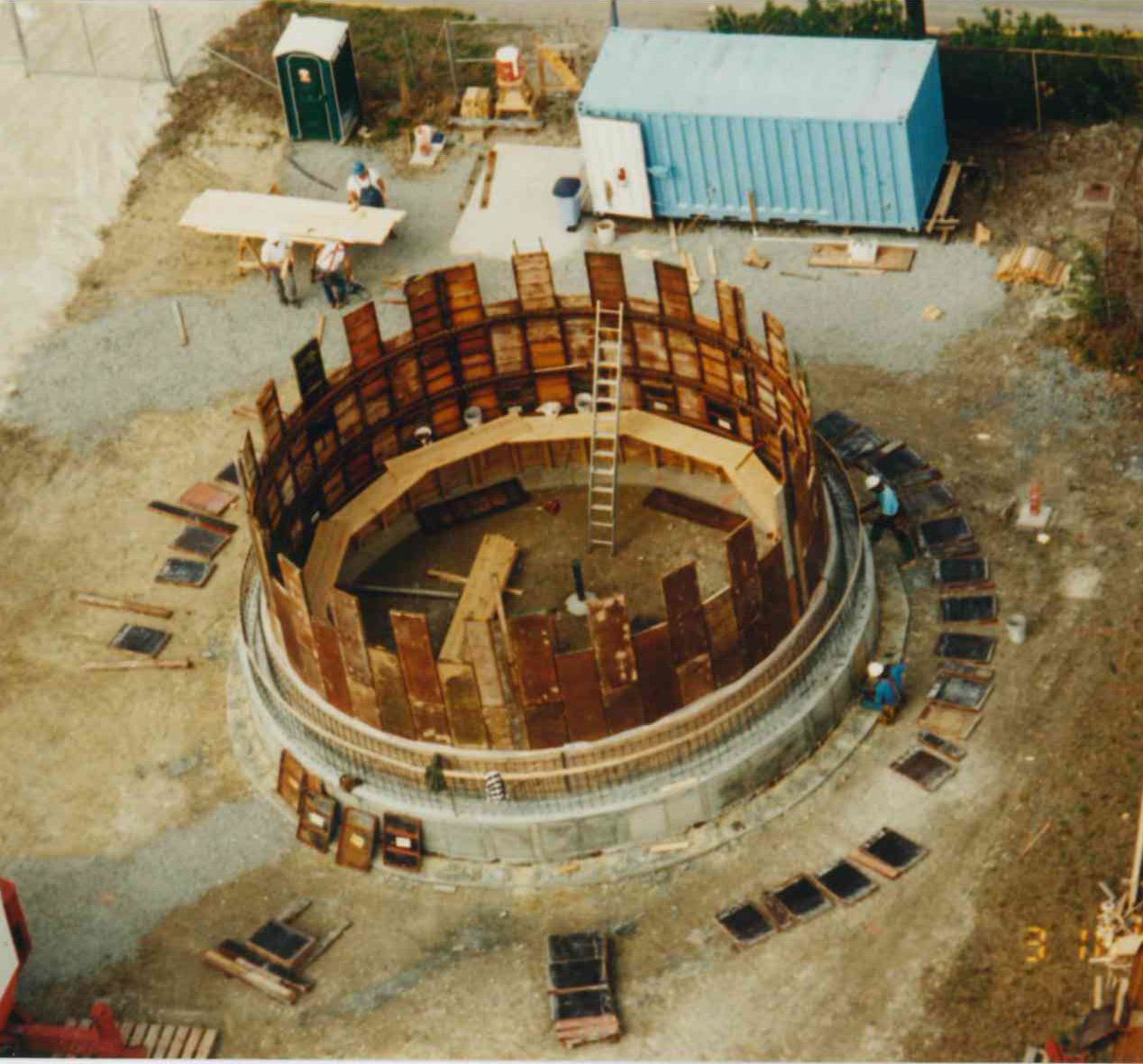
I'm designing a circular secant pile shaft. Some project info: Med-dense sand with silts, 115pcf, 33deg, 48' dia, 64' depth of excav, 4' dia piles. Some ring steel will be added to compensate for tolerances, but overall the walls are considered structurally competent to resist lateral loads by themselves. 12' pile embedment below bot of excav.

After the shaft is constructed, a few of the piles will see a significant axial load. For simplicity, I can assume that only the piles receiving direct contact with the load bear it down to rock. But will not some of this load also be transferred via pile-to-pile friction to the remaining shaft bearing surfaces on rock? I suppose that will only be the case to the degree that the contact piles settle... Is it legitimate to try to increase the effect bearing area with this logic, and if so, exactly how? Is there a reference I could look into?

I'm dealing with this because I was given no bearing capacity value for piles on rock, I just have skin friction allowables. We're assuming 10ksf for end bearing. Even though that seems overly conservative to me, we haven't needed the extra capacity until now. Now that this load is going to be acting on the piles, I might want to count on more bearing capacity in order to prevent an increase in embedment. So either I can say we actually have a larger allowable pressure than 10ksf, or I can say I actually have more bearing surface resisting this load.
 
Replies continue below

Recommended for you

What about asking the geotech for an end bearing value?
 
jayrod12

Project owner is a big municipality, and the geotech came from their consultant. So I like to limit the request for clarifications, extra info, etc. This is my first foray into deep foundations, so if allowable rock bearing value is something that should always be given geotech, then I suppose I just need to ask for it.

Just looked again at the report, and they give min, max, and avg unit weight (100, 156, 139 pcf) point load strength (0, 60, 12 psi) and unconfined compressive strength (234, 4594, 1072 psi)

Is the point load strength = bearing capacity? If so, my 10ksf isn't conservative.
 
How stiff is your cap beam? Can you use it to spread the point load to multiple piles?

I've once had a contiguous bored pile wall for a 6 storeys basement for a building which had columns directly supported on the cap beam. Since the loads were rather high and close to each other, we created a FEM model of the cap beam supported on springs to get axial forces on the piles and design the cap beam accordingly. It's only an approximation but better than assuming all load on one pile only.
 
avscorreia,

There is no cap beam. The piles are just resisting lateral earth, hydro, surcharge pressures while also providing water tight area for construction. This a temporary shaft for construction of underground facilities.

The vertical load is coming from a crane that can't be moved and whose mat will extend somewhat on top of the pile wall
 
Can you provide us a sketch?
If the mat is thick enough and it overlaps a series of piles it might distribute the load you need. Or a cap beam can created locally just to mobilise a few more piles.
 
Before I'd worry about figuring out how to distribute the load, I'd shoot an email or make a phone call to the geotech and find out what the end bearing capacity is. I wouldn't be surprised if it's a factor of 8 or 10, maybe more, greater than you've guessed.
 
hemiv said:
...64' depth of excavation...
...12' pile embedment below bot of excavation...
Some ring steel will be added...
...walls are considered structurally competent to resist lateral loads by themselves.
The piles are just resisting lateral earth, hydro, surcharge pressures while also providing water tight area for construction.

Pay more attention to the lateral loads. The piles (as structural elements) may be adequate for lateral loads, but it is unlikely the soil will be. Typically, 12' embedment is nowhere near enough to support heavy lateral loads on a 64' cantilevered wall... sure, there is some ring steel, but is it enough to resist all lateral loads by itself? IMHO, don't expect ring steel and cantilever support to share the load... design for one or the other to do it all.

Also, IMHO, framed circular cofferdams (excavations) are accidents waiting to happen. If lateral load is not equal around the circumference, the circular structure may be (without warning) catastrophically unstable. Get with the geotech before proceeding... and forget the (false) allure of minimum wall length (circular crossectional geometry) - go with square, or a caisson:

LGJV001%20-%20CAISSON%20AT%20CONCORD%202a%20%282%29.jpg


[idea]
 
I have never design a large circular shaft (if its similar to SRE's) picture. However the first thought I had was that 12ft embedment is definitely not enough! I hope you have a few rows of ring steal beams to add support.

If you are looking at using end bearing in rock you should use a high factor of safety to account for the large displacement (up to 20% of D) required to mobilize end bearing. We typically use factor of safety of 6. I have also seen end bearing being taken as 10% of its ultimate value. I accept its a temporary structure but i still wouldnt take any chances.
 
EireChch & SRE, for circular cross sections you really don't have a cantilever. It's all just a big compression ring. So it's not like a straight retaining wall where you need to mobilize passive pressure in order to balance the active pressure. As long as friction can prevent the walls from sliding down and if you're not concerned about seepage, I don't think you theoretically need embedment at all. We've seen examples of shafts like the one I'm designing be constructed with no ring steel at all, some of them published in engineering magazines. Our design does have ring steel and embedment, however, accounting for unbalanced loads and pile install tolerances.

EireChch, I ended up finding a section in my Das Foundation book that calculates rock bearing from unconfined strength. Section 11.13, pg 579 in the 7th ed. It basically takes lab unconfined values, divides by FOS of 5, then multiples by tan^2 (45+phi/2). Is this method related at all to your FOS of 6?
 
Like Avscorreia above, my experience with shafts like this have included cap beams that carried loads (mining headframes). Can your crane pad distribute this load over several piles? You don't want the crane pad to induce lateral loads, of course.
I think that you somehow have to get the Geotech involved.
Will you be monitoring the construction (by precision surveying or whatever) for movement during construction? Do you write these specs?
It does sound like a fun project. Make sure you get field duty on this one.
 
Hemiv,

I was applying my experience in non-ciruclar retaining walls and going with instinct re the embedment depth, maybe youre right. I dont have enough experience in circular shafts to comment any more.


Re Piles in rock

I checked Das reference and the factor of 5 on UCS is based on the scaling effect. The UCS value is 5 times higher than the actual value, so when you divide the UCSlab / 5 it becomes UCSdesign. I have never heard of that approach and I have only every seen it in Das. Maybe others can comment on its acceptance or usage?

I use Flemmings book for pile design. He recommends 3 x qu (Rowe and Armitage 1987) but also comments that Poulos and Davis (1980) use 0.3qu. Based on our local experience in soft rocks we use 2.5qu / 6 (FoS).

Piling Engineering 3rd Edition by Flemming et al. is a great reference, I would encourage any geotechs working with pile design to get it!

Capture_mhw5ig.png
 
EireChch, wow that's quite a wide spread. It looks like the Das book is similar to your method. The tan^2(45+phi/2) ends up being in 2-2.5 range. Thanks for the help, I'll check out that reference on pile design. It looks like I'm going to be doing a bit more of this stuff in the future. Which is cool! I wasn't expecting to get into this type of work but it's turning out to be a big compilation of all sorts of Civil principles - soils, water, construction practices, structural design, etc.
 
Status
Not open for further replies.

Part and Inventory Search

Sponsor