PSSC
Mechanical
- Feb 11, 2008
- 63
I had a bolted beam splice (channel), however due to things moving the bolted connection has to be removed.
My first option would be to simply weld flanges together in the field with a welded splice plate on the web.
For safety and other reasons I do not believe it would be possible to weld the bottom (tension) flange in the field.
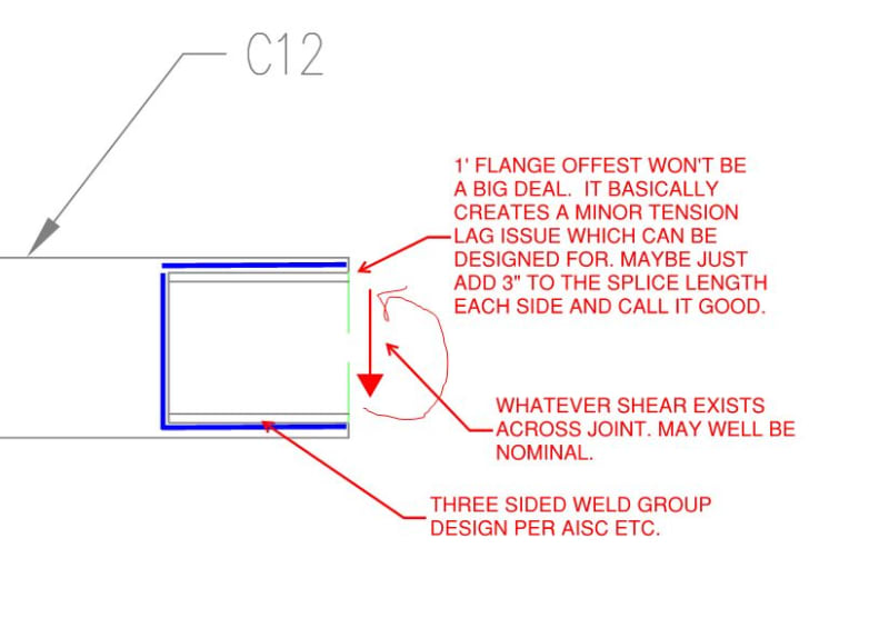
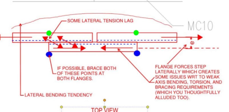
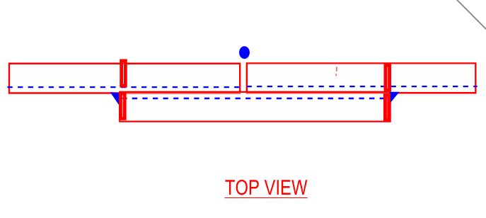
My next option is to weld a smaller in height but equally strong channel to the backside of the original channel, basically a MC10 welded to the back of a C12.
The connection has to resist moment and shear but is braced at the center.
My real points of concern are two things
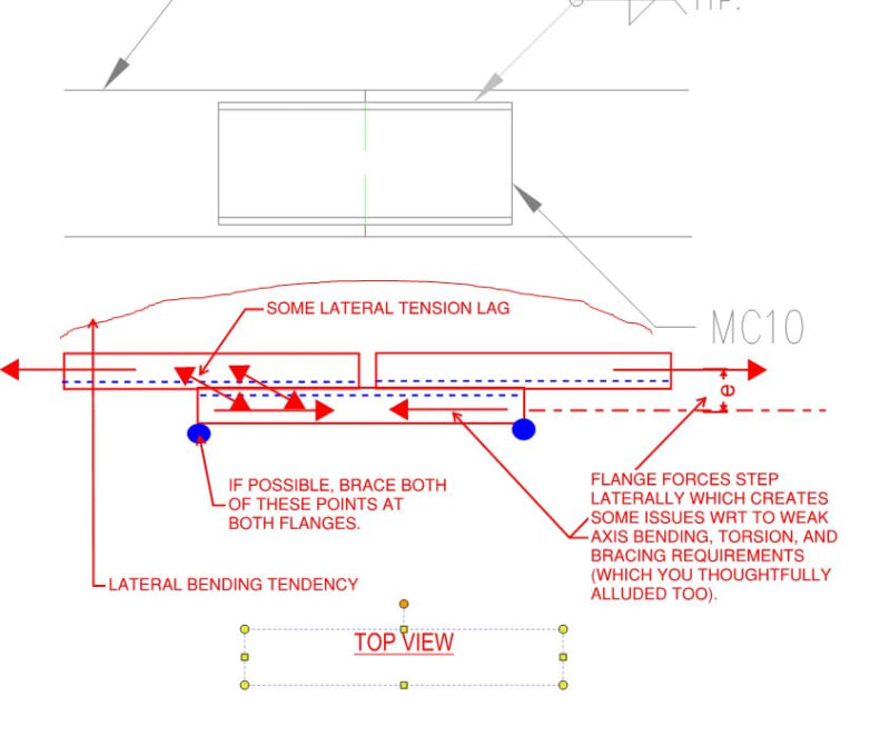
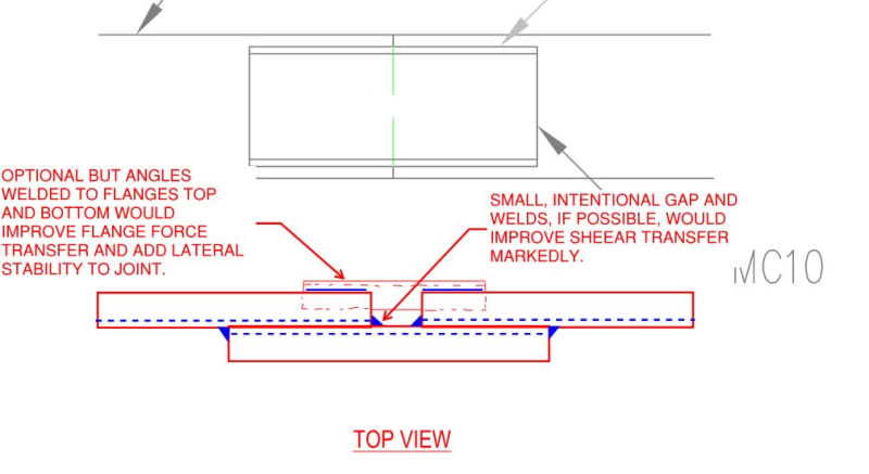
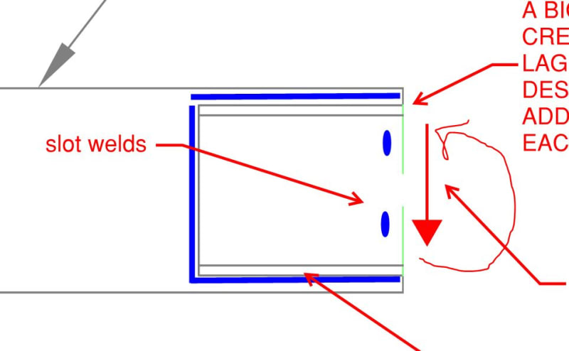
1, with a 1" gap above and below between the two channels flanges does the force transfer well from the C12 to the MC10? I had though of putting end cap plates on the ends of the MC10 that would extend to the edges of the C12. This is maybe overkill.
2, the weld, I have looked at this a few ways, I would rather just design the connection to handle the entire allowable moment for the C12. I have ran the weld calcs a few different ways, as a rectangle with the moment in the center and as two "C" shaped welds, these turn out to be the same thing after ran the numbers and actually looked at it.
Does anyone have any suggestion on the how to look at this weld or any other insight?
I have tried to attach a sketch.
thanks
My first option would be to simply weld flanges together in the field with a welded splice plate on the web.
For safety and other reasons I do not believe it would be possible to weld the bottom (tension) flange in the field.
My next option is to weld a smaller in height but equally strong channel to the backside of the original channel, basically a MC10 welded to the back of a C12.
The connection has to resist moment and shear but is braced at the center.
My real points of concern are two things
1, with a 1" gap above and below between the two channels flanges does the force transfer well from the C12 to the MC10? I had though of putting end cap plates on the ends of the MC10 that would extend to the edges of the C12. This is maybe overkill.
2, the weld, I have looked at this a few ways, I would rather just design the connection to handle the entire allowable moment for the C12. I have ran the weld calcs a few different ways, as a rectangle with the moment in the center and as two "C" shaped welds, these turn out to be the same thing after ran the numbers and actually looked at it.
Does anyone have any suggestion on the how to look at this weld or any other insight?
I have tried to attach a sketch.
thanks