Tek-Tips is the largest IT community on the Internet today!

Members share and learn making Tek-Tips Forums the best source of peer-reviewed technical information on the Internet!

  • Congratulations cowski on being selected by the Eng-Tips community for having the most helpful posts in the forums last week. Way to Go!

Chamfer

  • Thread starter Thread starter MACDAC
  • Start date Start date
M

MACDAC

Guest
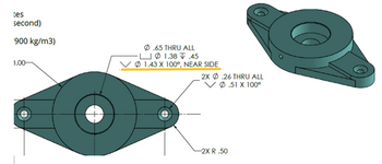
In this exercise, I´m asked to do what appears to be a chamfer, as viewed in this image
1646776817746.png

Now I have tried to use the chamfer option setting the distance to 0.025mm and an angle of 100° but the program says that they are building error due to geometry conditions.

I´m unaware if the chamfer feature is the optimal solution here, or is there another way of doing it.
 
The dimensions in the drawing are calling out a Countersink on the holes. That's what the 'V' symbol means. But, you are correct - it is like a chamfer on the edge of a hole.

However, a chamfer and a countersink are dimensioned totally differently. A countersink is dimensioned by the diameter at the largest part, and the total angle between both sides.

I believe you should be able to add the countersink as part of the Hole Wizard tool in Solidworks.

Or you could continue to use a chamfer, but the dimensions will be .025 X 40°.

(by the way, all the dimensions are in inch units, unless this part is very small)

I hope I helped
 
Last edited:

Part and Inventory Search

Sponsor

Back
Top