M
MechEngFta
Guest
Hello,
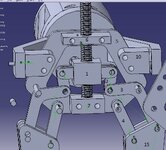
I am new to this forum and beginner in Catia. I have a problem and I need your valuable help! I designed a gripping mechanism, and I am in the process of creating the joints in order to simulate its motion, but for some reason it doesn't work the way I want it to. I am attaching a pic with the design so far
View attachment 1452.
I hope it does get uploaded...So, I have made rigid joints between parts 5, 6, 7, 8, 9, 10 and the screw. (I am only describing one side, the other side is mirrored obviously...)And I have added a cylindrical joint between the screw and part 1(I want it to move only linearly though). Part 1 and rod 11 have a rigid joint as well, and so do part 2 and rod 12. Then I created a revolute joint between 11 and 2, and between 12 and 3. So far so good. It moves perfectly. Then, I wanted to make a revolute joint between 3 and 9 but it wont let me go on with the simulation any more. It says "The created command has no effect on the degree of freedom of the mechanism". The motion I want it to perform is this. As part 1 goes linearly up and down, part 15 closes and opens. rod 9 is fixed and part 3 revolves around it. Do you have any idea how I can fix that?
Thanks in advance!