Tek-Tips is the largest IT community on the Internet today!

Members share and learn making Tek-Tips Forums the best source of peer-reviewed technical information on the Internet!

  • Congratulations MintJulep on being selected by the Eng-Tips community for having the most helpful posts in the forums last week. Way to Go!

Catia Generative Structural Analysis Body issue

  • Thread starter Thread starter Oasis
  • Start date Start date
O

Oasis

Guest
Hello everyone, I am an engineering student, I didn't work a lot with catia so I am messaging you to get some help on a problem I have using the structural analysis module.
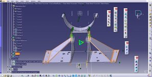
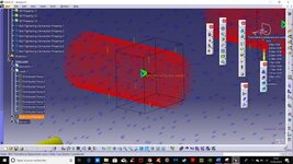
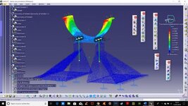
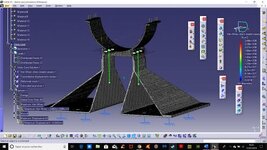
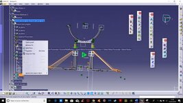
Here is my problem, I want to make a simulation on a product I made (it's a mount for an engine test in a wind tunnel). The issue is one of the part of this product contains several bodies, but when it comes to mesh, I can only mesh the "Partbody", not the Body.4, and I don't why.
So I am waiting for advice and suggestions.
Best regards
NB: the Body.4 is the one I selected on the screenshot
 

Attachments

  • Capture.jpg
    Capture.jpg
    25.2 KB · Views: 8
If you want to analyze all the bodies as a single part;

In the tree, right-click on a Body.x and choose the ADD option. This will add the Body geometry to the Part Body geometry. Repeat for all the other bodies until everything is added to the Part Body. Now you can create the mesh of the entire mounting bracket.
 
Last edited:
Thanks for the reply, but the thing is I don't have the ADD option when I right-click on Body.3 (for instance). View attachment 2256
 

Attachments

  • Capture d’écran (1).jpg
    Capture d’écran (1).jpg
    24.9 KB · Views: 5
MrCATIA I just found out I had to click "Edit" first, so don't take the previous reply into account
 
So I created the mesh for the mounting, and the screws. I added a contact constraint between the screws and the mounting bracket with 200N as a tightening force. But I don't understand why CATIA gives me 10^4mm of desplacement in the perpendicular driection of the force exerted on the screws. They are not supposed to move at all towards this directionView attachment 2257

Problem solved
 

Attachments

  • Capture d’écran (2).jpg
    Capture d’écran (2).jpg
    26.9 KB · Views: 5
Last edited:
Here is the result. All is grey concerning von Mises, the displacements are displayed as I expected. So, any ideas on how to display the colors for von Mises ?View attachment 2259
 

Attachments

  • Capture d’écran (3).jpg
    Capture d’écran (3).jpg
    26.7 KB · Views: 4
  • Capture d’écran (4).jpg
    Capture d’écran (4).jpg
    27.8 KB · Views: 5
Last edited:
Ok, so found out how to display it properly. Still need to hide every thing except the screws cause the highest constraint is there. I'll probably find out myself, so thanks again for the answer, and I'll have to figure out how to close the thread now, should be easier.
 

Part and Inventory Search

Sponsor

Back
Top