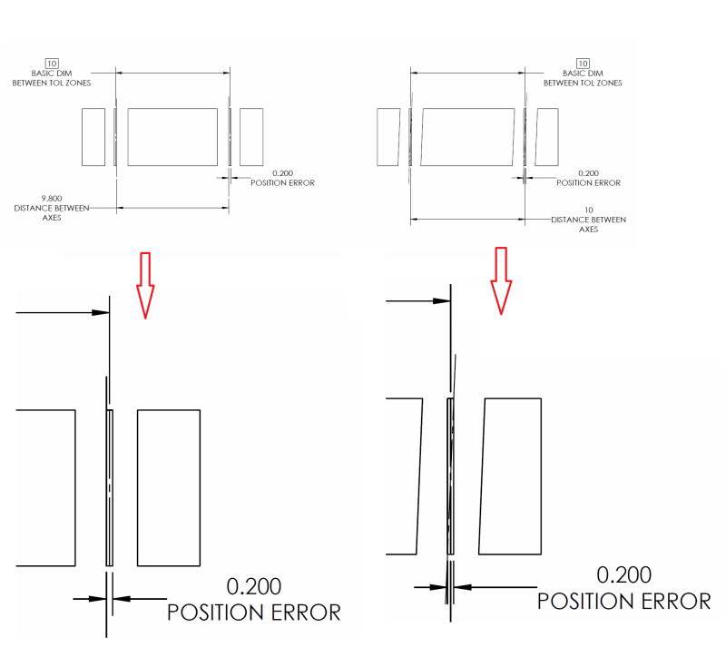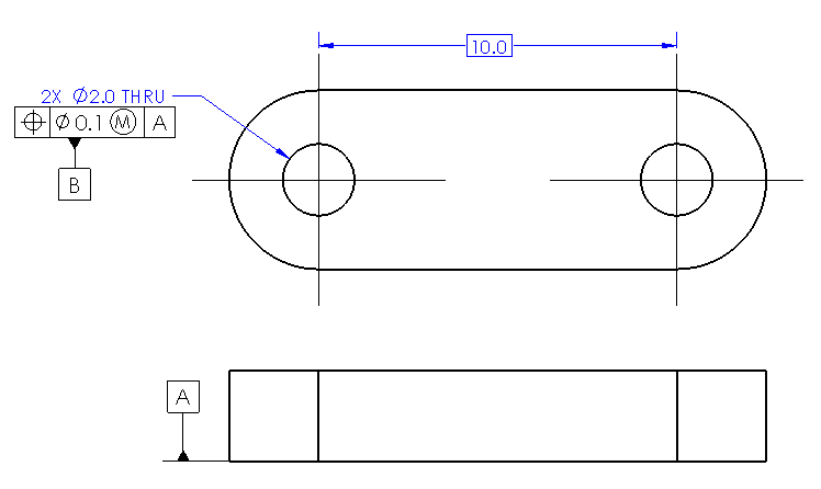
Given the attached example, how would the true position tolerance be calculated on the pair of thru holes? Is it simply the error in their linear basic distance or does it have to do with their three dimensional forms (i.e. perpendicularity as well)? And a follow-up: where would the alignment be located for any other feature when referencing these two datums? Would it be the centroid between the two holes using the line between them as a skew direction?