Tek-Tips is the largest IT community on the Internet today!

Members share and learn making Tek-Tips Forums the best source of peer-reviewed technical information on the Internet!

  • Congratulations cowski on being selected by the Eng-Tips community for having the most helpful posts in the forums last week. Way to Go!

Buckling with Inertia Relief

Senophoe

Student
Joined
Jan 31, 2025
Messages
4
I know this question has been asked a few times. I'm sure I checked almost every answer avaiable around. But I'm still having trouble using SOL 105 buckling with inertial relief.

Here's the .nas/.dat Nastran file: https://drive.google.com/file/d/1RrH_hMMeLpE3qEWH_Ea3nuVQBoBBindj/view?usp=drivesdk

Here's the error I'm having in the buckling set, from the f06 file:

1751574485789.png

I have INREL set to -1 in the Bulk Data:
1751574714898.png

I also have SUPORT1 defined in the Bulk Data:
1751574750904.png

And finally I'm running a STATIC SUBCASE with SUPORT1 and then calling it via STATSUB in another SUBCASE for buckling.

1751574806335.png

What am I doing wrong?

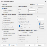
Photos of the setup.

1751574895810.png
1751574923658.png
1751574957000-png.14826


The model is a LAMINATE composite tube with two RBE3, each with a load in the center node. I put the SUPORT1 constraint in a random node restricting 123456 dofs, just for test.

1751577728012.png
 

Attachments

  • 1751574957000.png
    1751574957000.png
    39.2 KB · Views: 14
Last edited:
Just a guess: Does your SUPORT1 node have the ability to take moments? The 456 on the support card basically require that point to have that ability.

Does your model have solid elements? Is the SUPORT1 node attached to only solid elements? That might be the problem. Solid elements cannot take concentrated moments., and you cannot support a rigid body about a point that cannot take moments.

I believe the SUPORT card allows you to apply rigid body restraints at different nodes, for example: restrain DOF=123 at one node, DOF=23 at another, and DOF=3 at a third (not all one a line). Then those 6 translational restraints serve to provide rigid body support in all 6 DOFs.
 
Just a guess: Does your SUPORT1 node have the ability to take moments? The 456 on the support card basically require that point to have that ability.
I uploaded the .nas/.dat file below. The model is a hollow cylinder. The skin is meshed with LAMINATE elements. I suppose those are capable of taking moments.

I put the SUPORT1 in one node in the skin. I did that just for testing.

Here's the .nas/.dat file with the model and complete analysis setup. Would you kindly help me out figuring out my mistake?


Does your model have solid elements? Is the SUPORT1 node attached to only solid elements? That might be the problem. Solid elements cannot take concentrated moments., and you cannot support a rigid body about a point that cannot take moments.
I didn't use solid elements. The SUPORT1 node is a single nodal point in the cylinder skin. The structure is a hollow cylinder meshed with LAMINATE elements.

I believe the SUPORT card allows you to apply rigid body restraints at different nodes, for example: restrain DOF=123 at one node, DOF=23 at another, and DOF=3 at a third (not all one a line). Then those 6 translational restraints serve to provide rigid body support in all 6 DOFs.
I'll read Nastran documentation on how to do that using SUPORT1 card tomorrow. It's late night here now.
I suppose I'm allowed to have a single SUPORT1 entry in the Case Control section, which refers to a single SUPORT1 in the Bulk Data section. So I'm guessing I can simply modify my Constraint used as SUPORT1 to have different constraints at three different nodes.
 
Last edited:
Sorry I don't have the software to look at the model, I can only read the text file. So I am still "only guessing".

If possible, the idea of supporting the model at only translational DOFs at 3 distinct points might work. Note that SUPORT and SUPORT1 are different cards.

My first question should have been: have you checked the model with a simple linear static run? This will ensure there are no other issues before attempting the INREL run. Set up a simple load/BC case and make sure it runs and the deflections and other results look reasonable.

I see you have no solid elements, so my initial guess there was wrong. But CQUAD4 elements cannot take twisting moments normal to the element surface. [Example: If you had a flat plate modeled in the x-y plane, these elements cannot take Mz.] For your cylinder, these elements cannot take moments about the outward normals to the cylindrical surface (might be your global y or z axis or a combination depending on where around the perimeter the point is). If you decide to pursue this, you could add a ring of CBAR elements around the circumference at the location where you currently have your SUPORT1. Since your thickness appears to be 2.4, you could make the bar a square cross-section of dimensions 2.4x2.4. This would add rotational stiffness that the shells do not have - perhaps enough to get the model to run but not enough to seriously affect the results.

But the previous suggestion of supporting 3 nodes translationally is probably the best bet if you can get that to work (and your simple static runs shows no other issues).

If nothing works, another option might be to apply the inertia loads directly rather than using INREL to compute them. From the mass of your model and the known applied loads, you could back out the accelerations and apply them using GRAV and/or RFORCE cards.
 

Part and Inventory Search

Sponsor

Back
Top