Tek-Tips is the largest IT community on the Internet today!

Members share and learn making Tek-Tips Forums the best source of peer-reviewed technical information on the Internet!

  • Congratulations TugboatEng on being selected by the Eng-Tips community for having the most helpful posts in the forums last week. Way to Go!

Bowstring Steel Pedestrian Bridge Connection Details (Top and Bottom Transverse Members and Diagonals)

Farhaad Shaik

Structural
Joined
Mar 25, 2024
Messages
5
Location
ZA
Evening Colleagues,

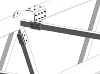
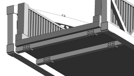
Please can someone advise on how do I arrange the bolts at the splice position to transfer moment.

There is a very small moment but nevertheless needs to be catered for.

The structure is a steel bowstring pedestrian bridge that is envisaged to be put together on site.

No site welding is allowed therefore, the 4 truss segments are bolted together.

Can someone assist me with how to arrange the bolt connection at the diagonals, top and bottom transverse members as the current setup feels over designed.

The diagonal and top transverse members are 120x120x5 square hollow sections and the bottom transverse members are 150x150x8 square hollow sections.

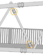
1750782872389.png1750782912447.png1750782946626.png1750782971637.png1750783005356.png
 
1. Flanges may be an option, though apparently require modification to the existing works, and
2. Please consider requesting others to assist, as this request is "unexpected" in general.

Regards.
 
Tubular sections look so clean on paper, but they are a bear to erect in the field. How does one place the bolt or nut w/ washers in the closed connection? To say there is limited access is an understatement. If the nut is tack welded inside the HSS, how does the erector use drift pins or spud wrenches to align the holes without damaging the threads? If the bolts are placed and tack welded inside the HSS, how are the members handles so as not to damage the threads?

Everything looks nice on paper, but it is a different story in the field.
 
I think these look really ugly and will be an absolute bitch to install unless the ends are cut super accurately and square and the bolts drill within 1mm of where they are supposed to be.

Have you thought about internal box sections which extend say two or three times the lengths of your plates and then just secure them with say four bolts either side to stop them pulling out? you might need to come up with a way to slide the connecting box section totally inside one of the elements and then move it.

Internal sleeves would look nicer but might not easy to install unless you can adapt the sequence and build it from one end or the middle out.

Or make it an external sleeve instead?

Then you could fill in the gap between the ends of the main spars with sealant.
 
Or consider pin connections like those used for a crane boom.
 

Part and Inventory Search

Sponsor

Back
Top