Continue to Site

Eng-Tips is the largest engineering community on the Internet

Intelligent Work Forums for Engineering Professionals

  • Congratulations waross on being selected by the Eng-Tips community for having the most helpful posts in the forums last week. Way to Go!

Bottom Flange Loading of Perimeter Floor/Roof Beam

Status
Not open for further replies.

mtuhusky

Structural
Jun 18, 2011
13
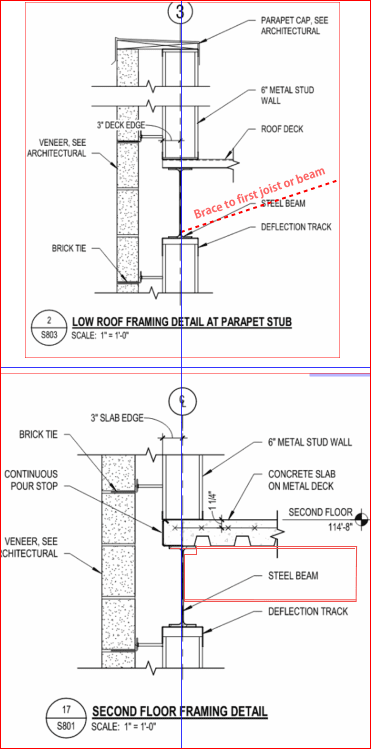
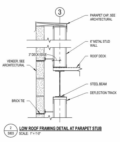
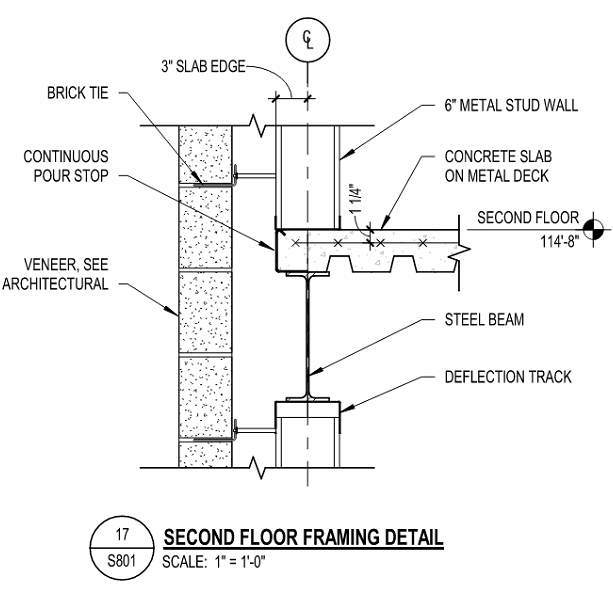
I often work on building designs in which the exterior structural steel is hidden inside a metal stud wall. This means that the cladding system consists of a continuous metal stud wall spanning vertically between each floor. The metal studs below the beam are framed into the bottom flange of a W-Shape and transfer wind load into the beam's bottom flange. This generates weak-axis bending and torsion in the beam. The top flange of the beam would be considered laterally braced by the floor or roof diaphragm. The beam would typically have a simple shear connection at each end, often a shear tab.

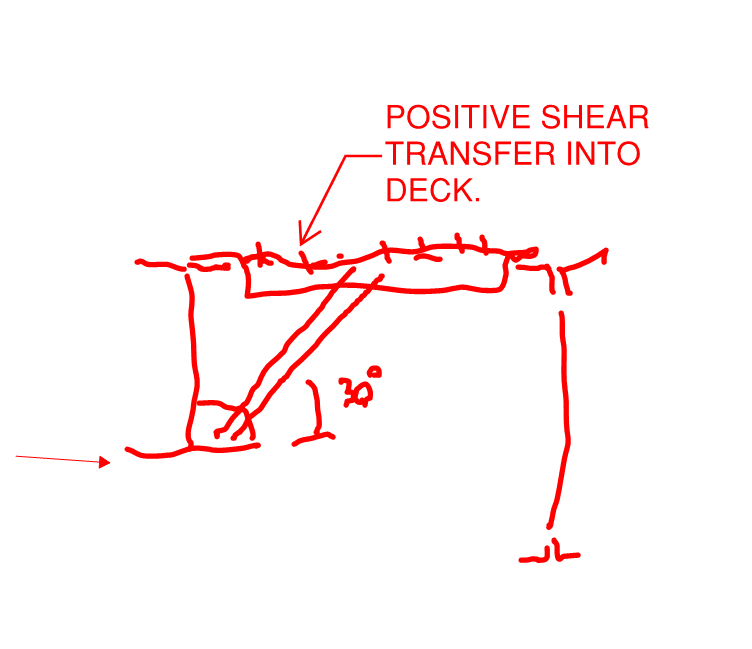
I'm curious to know how other engineers approach the design of this type of beam.All of the design examples I've seen for W-Shapes involve an eccentric vertical load that creates torsion and assumes the beam rotates about it's centroid. But in this specific case I would think the beam would rotate about the top flange. I've attached some example details for more clarification.

Capture2_ufqygy.png
Capture1_wout1i.png
 
Replies continue below

Recommended for you

I think it's usually resolved with kicker braces, which are typically hidden above a suspended ceiling.
 
At Roof Level, I would brace to the first joist or beam as shown below.

At Second Floor Level, I would do the same when deck is normal to the beam, but for direction shown, beams or joists supporting deck should provide adequate torsional resistance.

Capture_kpqnsr.png


BA
 
I usually check the bottom flange in bending laterally and provide kickers as required to keep the desired beam size working. Usually I use 1/2 of the weak axis section modulus.

In a rare case, I would be inclined to disagree with BA regarding the joists providing the torsional resistance. That would only be the case if they strutted the bottom chord of the beam to the joist (note: most joist suppliers prefer if the struts for situations like that go to the top chord panel point instead of strutting to the bottom chord of the joist).
 
I agree with the kickers or other means of torsional restraint mentioned above for the beam rotation. What stands out to me in your detail is the parapet.. Maybe that is an incomplete detail, but I am not seeing how you are planning on stabilizing the (cantilevered?) parapet studs which appear to be setting directly on the metal deck. You may have just posted some images from google, and if so sorry I hijacked your thread, but that definitely stands out and I hated not mentioning it.
 
jayrod12 said:
In a rare case, I would be inclined to disagree with BA regarding the joists providing the torsional resistance.

If the joists are O.W.S.J., bottom chord extensions would be required, but they can't be O.W.S.J. on the OP's section, or the beam would be lower down to make room for the joist shoe.

Also, I just noticed; I don't like the parapet detail very much. Can't say I have ever seen that detail, but the parapet is not particularly well connected for wind moment.

BA
 
Fair point, I assumed the section was cut along a wall parallel to the joists, but as I look closer I see that with the deck span the way shown in that floor section, I would expect hot rolled flush framed joists and would agree that would be adequate torsional resistance. The roof section probably gave me the impression we were looking at beams parallel to joists.

Also agree with the others regarding the parapet detail. Generally speaking we've never been able to get cantilevered steel studs to work for any parapet taller than 24". And that's typically due to anchorage issues, not member strength. WE often have regularly spaced angles welded to the top of the beam.
 
1) Put me down as another vote for kickers and roll beams.

2) In some, open ceiling applications where a cleaner look has been desired, I've added what amounts to a wind girt at the bottom of the beam using one of these strategies:

a) Design the bottom flange as a girt such that combined stresses work when the girt function is combined with the gravity function.

b) Weld an upturned channel or HSS on to the bottom flange to be a girt.

3) I've been thinking about this detail recently. Common versions of it often neglect the positive shear transfer into the deck in my opinion. I feel as though a good version of this detail would be as I've shown below. To date, I've not seen it done this way however. If the positive shear transfer is dealt with at all, it's usually with a horizontal angle in the adjacent joist/beam space.

c01_nm1q4h.png
 
The parapet studs are braced with kicker studs, that is not shown in these details. The parapet is irrelevant to the original post though. I'm just trying to illustrate the condition at the bottom flange. I agree that floor beams would provide torsional resistance if they are a similar depth. I also agree with bracing the bottom flange of the beam to the floor or roof above if the beam does not have the capacity to resist the torsion. The question is how do you determine the spacing of the braces? You still need a way to calculate the torsion capacity of the beam. I like the idea of checking the bottom half of the beam for weak-axis bending, but how accurate is this? Is it conservative or unconservative?
 
I'm not theoretical enough to know if it's conservative or unconservative. It's just the way I was taught to design it and logically made sense to me. So I never really questioned it.

to be fair, I rarely take my beams beyond 90% capacity for gravity design, and I'm fairly conservative on my bottom chord brace spacing. I.E. if I've calculated a required spacing of braces around 10 feet, but the beam is 25 feet long, I'm providing two braces at 1/3 points which if you take continuity into account results in a substantially lower moment than the allowable spacing I calculated using wl^2/8.
 
Check out chapter 6 of AISC Design Guide 22 for some procedures on spandrel beam design, including torsion.
 
One simple and conservative way to prosecute the design would be this: double your flange lateral load, apply it to the beam shear center, and do a biaxial flexure design per the normal procedures in your neck of the woods.
 
When I was doing CFS design, I regularly saw the same detail without kickers or any other means to brace the bottom flange. I usually mentioned it to the EOR. Not sure if they ever did anything about it.
 
I second the "double-the-flange-couple-and-apply-to-the-full-section-in-weak-axis-bending" method mentioned by KootK above. I use it fairly regularly to estimate torsional resistance. If you would like some semi-applicable design guidance, the method is mentioned in the AISC article "Design Concepts for Jib Cranes" for resolving jib crane torsion in columns.

 
I found this note in design guide 22:
"As an alternative approach, the torsional effects and rotation of the beam can be calculated using a “flexural analogy.” This method converts the applied torsion into a force couple acting at the top and bottom flanges of the beam. The force at the top flange is resisted by the deck. The force at the bottom flange is resisted by weak-axis bending of the bottom half of the spandrel beam."

It then goes on to say that, for longer spans, this method is approximately 1.7 times more conservative that the method presented in design guide 9. The calcs in design guide 9 are very cumbersome.
 
Status
Not open for further replies.

Part and Inventory Search

Sponsor