L
Luru
Guest
Hello everyone,
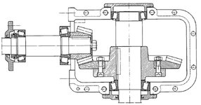
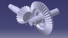
I have problems with my bevel gear model. I have to design the parts in the attached pictures. They are 2 shafts with a Pinion and a Gear. I also want to simulate the motion with the Kinematics. The first shaft moves with the pinion and the gear moves consequently with the other shaft. View attachment 2412
I have followed the following tutorial for the design of the bevel gears: https://www.youtube.com/watch?v=uOAoR6VycKA&t=4068s
With this tutorial I have also understood that the shaft in catia must be in the same "Part" and you cannot create two different parts: "Shaft1" and "Shaft2"... I really don't understand why
I have put the two shaft in the same part (following the aforementioned tutorial) and I am able to simulate the mechanism, even though with a lot of problems :
The first one is that the mechanism is with intersections, the two gear interfere with one another and don't move together.
Moreover another problem is that to design the Shafts I had to put some constraints inside the sketchs of the shaft, but when I try to simulate the mechanism I receive the error "Mechanism cannot be simulated becouse is over constrained" and I don't understand why...
If someone would be so kind to try to help me, you can reply under this thread or send me a PM for more informations.. I can send you the parts and the product so that you could see with your own hands what's going on..
ThanksView attachment 2413