Continue to Site

Eng-Tips is the largest engineering community on the Internet

Intelligent Work Forums for Engineering Professionals

  • Congratulations Ron247 on being selected by the Eng-Tips community for having the most helpful posts in the forums last week. Way to Go!

Best practice for connecting existing trusses and rafters to a proposed I-beam header.

engineer_123

Structural
May 23, 2024
17
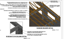
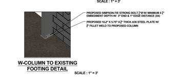
Cleaning up another engineer's mess. Previous engineer showed insufficient data, such as connections of existing roof framing to I beam, and how I-beams connect together and at concrete base. Their diagram, they have roof framing flush with I-beam, i.e. using hangers. I want the proposed flat roof rafters, and existing trusses to bear on top of the proposed I-beam header and then use a 2x6 Nailer installed on top of the I-beam header, matching the web distance, and use some sort of hurricane strapping & blocking to connect everything together. What have you done for these, I've always used wood headers such as lvl. See attachments, thank you.
 

Attachments

  • I-beam cross-section temp.png
    I-beam cross-section temp.png
    74.2 KB · Views: 105
  • I-beam Plan temp.png
    I-beam Plan temp.png
    78.2 KB · Views: 103
Replies continue below

Recommended for you

Man, those drawings are pretty bad. Are they actually done by a PE?
You can make it flush or dropped.
Dropped is my preference basically as you described.
 
Yeah, those drawings suck. If those were made by a PE, then whoa! Calling out steel sections by width and depth instead of by AISC designation and calling a column an I-beam are a couple of red flags that someone is probably clueless and unqualified.
 
Man, those drawings are pretty bad. Are they actually done by a PE?
You can make it flush or dropped.
Dropped is my preference basically as you described.
Yes, a PE made these. You prefer dropped, maybe you can provide some specifics, if the flat roof rafters are 2x8s and the trusses are 2x6s how would you connect these?
 
Yeah, those drawings suck. If those were made by a PE, then whoa! Calling out steel sections by width and depth instead of by AISC designation and calling a column an I-beam are a couple of red flags that someone is probably clueless and unqualified.
Yes, a PE made these. And these plans are after the fact, so I believe they did use an I-beam header and columns. You have any advice to clean this up?
 
Yes, a PE made these. And these plans are after the fact, so I believe they did use an I-beam header and columns. You have any advice to clean this up?
You'll have to be more specific. In general, design the members and connections, and draw the details.
 
If the flat roof is 2x8s, the PE is calling a flat roof, a flat truss. In my state, most stamps say Professional Engineer, but it does not say what kind of engineer. I think we have an electrical engineer in this case.

Do you mean this has already been built, or is it still in the planning stage?

Is the header allowed to be dropped below ceiling level?
 
I agree with the comments above. These plans are rather bad. If this is (or was) new construction, I'm not sure what the "PE" was thinking designating a beam as 6" wide by 15" deep. This would have to be an S section which isn't commonly used in new construction.

And these plans are after the fact, so I believe they did use an I-beam header and columns. You have any advice to clean this up?
If this has already been constructed in part or in whole, the advice is to go there and measure what's actually been constructed. With plans this poor, this could be almost anything.
 
These plans are comically bad... so bad that this PE should probably be reported for practicing outside his area of expertise
 
If the flat roof is 2x8s, the PE is calling a flat roof, a flat truss. In my state, most stamps say Professional Engineer, but it does not say what kind of engineer. I think we have an electrical engineer in this case.

Do you mean this has already been built, or is it still in the planning stage?

Is the header allowed to be dropped below ceiling level?
Already constructed, and they used the steel beams. Building department wants after the fact plans corrected.
 
I haven't reviewed or verified your design in detail, but at first glance, I would recommend that you draw traditional 2-D details instead of your fancy 3-d BIM model. For example, your beam-to-column detail is essentially unintelligible because you can't see the actual components being referenced by your leader callouts. It leaves a lot of room for interpretation and error. Your drawings are an improvement over the other guys crap drawings, but they still leave a lot of room for improvement.

Plus, is this proposed, as you say in your drawings, or existing, as you say upthread?
 
Thank you for the critique. I do some details in 2D, I just like the look of 3D. One of the issues I've had with 2D, is you don't know if its "going to fit". If you draw it all out in 3D, it leaves out all questions. Yes, this is after the fact, but I still need to differentiate between what was there before items were constructed. what other term to use than proposed?
 
Thank you for the critique. I do some details in 2D, I just like the look of 3D. One of the issues I've had with 2D, is you don't know if its "going to fit". If you draw it all out in 3D, it leaves out all questions. Yes, this is after the fact, but I still need to differentiate between what was there before items were constructed. what other term to use than proposed?
You may like the look of the 3D model, but I guarantee the contractor won't.
I typically use "new" instead of "proposed" I like my drawings to have as few words as possible. No need to say "strong tie" - Simpson is fine. No need to say "thick" on the plates - everyone knows what you mean.
 
Since you are calling out the steel W-sections properly, I would not include the overall dimensions. If they are qualified to handle steel, they should be able to figure that out.

I would not call out 2-2"x6" since the correct designation is 2x6. I might show it as (2) 2x6s or two 2x6s. The more numerals you show in a row gets confusing for me to read. I single note saying "all lumber is dressed or S4S UNO" would cover dressed versus actual.
 
I try not to label things as "New" or "Proposed" on drawings, only existing. The implication is that if it's not labeled 'existing' it is new. That way, if I miss such a label, it's something the contractor doesn't have to buy rather than an omission that results in an extra charge.

Also, I'm a big fan of using 3D or isometrics for context. BUT...they should supplement traditional detailing, not be the primary and especially not the sole method of conveying the design intent.
 

Part and Inventory Search

Sponsor