Jalbno
Structural
- Nov 11, 2020
- 6
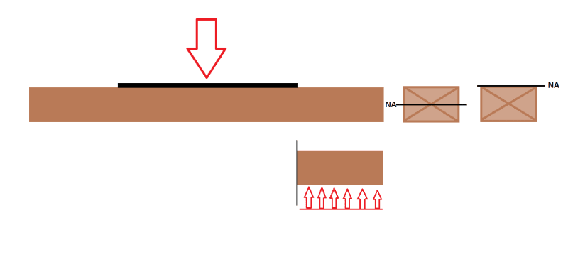
Hi everyone, I have a scenario where a plate is bearing on a 2x12 lumber.
I am analyzing the bending in the bottom timber as a cantilever from the edge of the plate.
The bending resistance of the timber is Mr = Material Factor * S * Fy
My question is what I should use for the section modulus. I assumed bd^2/3, with the neutral axis being in the middle of the beam.
A colleague of mine is confident that the section modulus should be bd^2/6, with the section modulus being at the edge of the beam because it is bending around the plate.
any ideas or clarifications?