Tek-Tips is the largest IT community on the Internet today!

Members share and learn making Tek-Tips Forums the best source of peer-reviewed technical information on the Internet!

  • Congratulations cowski on being selected by the Eng-Tips community for having the most helpful posts in the forums last week. Way to Go!

Beam Reinforcement Calculation

Nick6781

Structural
Joined
May 15, 2024
Messages
52
Location
CA
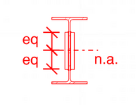
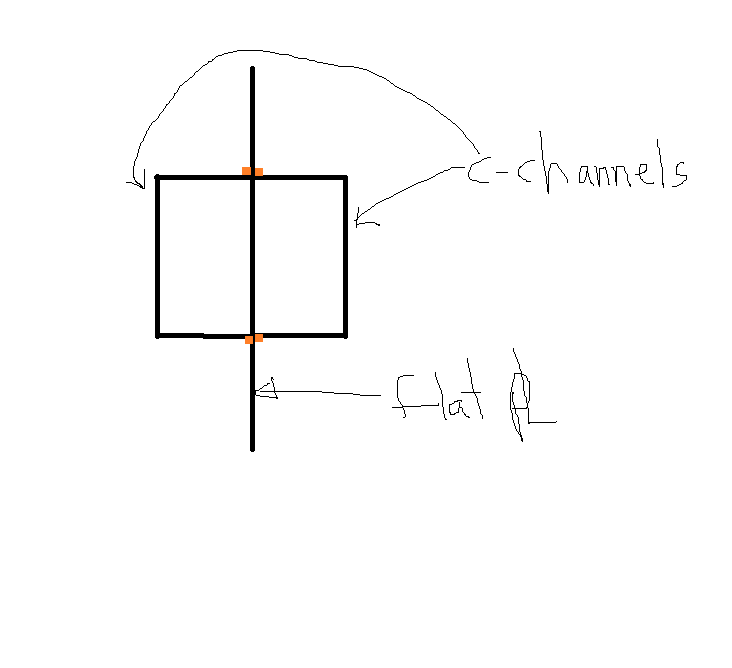
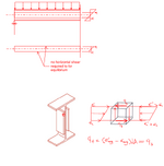
Let's say I need to use a web plate instead of a flange cover plate (I know...) to reinforce a beam. How do I calculate the required weld to ensure the section acts compositely? The shear flow equation gives the shear along a horizontal plane, but in this case, the faying surface is vertical. I can't quite wrap my head around it.


1751068113227.png
 

Attachments

  • 1751068099044.png
    1751068099044.png
    12.3 KB · Views: 1
Is this for repairing a corroded beam or reinforcing it for an increased shear load? If it's purely for bending, the increase in capacity here is going to be small so I can't imagine it's even worth it. When the centers line up shear flow is greatly simplified. You just have to design the connection to take the shear at any particular point. Then when the reinforcing ends, you have to get the shear back into the original member to transfer it out to the supporting column, bearing wall, etc.
 
Using web plate helps in resisting shear stresses mainly, while using flange cover plate helps in resisting mainly bending stress, so basically you cant use one instead of the other. Everyone has its own use. Be careful.
You can calculate how much shear the additional web plates can carry, and design your weld based on that.
 
Likely cheaper to replace the beam. Need more background on what the actual issue is
 
I would use the shear flow formula, VQ/I, to determine the load per lineal foot in the weld. Then design the weld accordingly.
 
I suppose the question is how to calculate the required fillet weld thick. and stress so the section acts compositely rather than effectiveness of web stiffening .
The shear flow equation gives the shear along a horizontal plane, but in this case, the faying surface is vertical.
Using the shear stress formula ( at Mr Atkins' respond ) you can calculate the horizontal and vertical shear stresses. Moreover , you need to design the fillet welds still for horizontal . The following figure from the book Mechanics of Solids, by POPOV.


1751180763018.png
 
Is there really any actual "shear flow"? If the plates are symmetric and centered top to bottom it is just addiitve stiffness so the welds only need to be sized to transfer the load based on relative stiffness - which should be quite minimal. Channels would be more effective.
 
All the centroids and neutral axis locations would be in line with each other so I agree with @XR250, really just need enough weld to get load into the new plates.
 
Is there really any actual "shear flow"? If the plates are symmetric and centered top to bottom it is just addiitve stiffness so the welds only need to be sized to transfer the load based on relative stiffness - which should be quite minimal. Channels would be more effective.
I agree. This is what I was thinking. It's similar to the flitch beam situation, except that the plates do not have their own end supports.
 
Is there really any actual "shear flow"? If the plates are symmetric and centered top to bottom it is just addiitve stiffness so the welds only need to be sized to transfer the load based on relative stiffness - which should be quite minimal. Channels would be more effective.
I also agree but might add that lateral bracing of the plate members by the existing section should be considered as well.
 
I agree. This is what I was thinking. It's similar to the flitch beam situation, except that the plates do not have their own end supports.
Which is why I mentioned above that you just have to get the shear out of the ends back into the main member for support. So because it's a partial reinforcement you have to get the shear into these plates then back out.
 
Is there really any actual "shear flow"? If the plates are symmetric and centered top to bottom it is just addiitve stiffness so the welds only need to be sized to transfer the load based on relative stiffness - which should be quite minimal. Channels would be more effective.
Yes, there is. VQ/I is the shear flow for the existing beam plus two new plates where Q is taken at top (or bottom) of added plates.

If w is web thickness and t is the added plate thickness, then each weld must resist VQ/I * t/(w+2t).

It turns out that Q is unchanged by the addition of two plates, but Icomp = Ibeam + 2tddd/12 where d is plate depth.

I agree with others that the addition of plates would be difficult to justify.
Well, it looks like you argued this before, BA. I don't buy it.
 
Well, it looks like you argued this before, BA. I don't buy it.
Really, any particular reason?
 
For the sake of discussion, the first diagram shows a uniformly loaded beam cut in the middle (shear=0 at midspan). We understand that shear flow is contributed by differential moment along a given beam length. Draw a FBD of the side plate and just look at the horizontal forces, the horizontal normal stresses due to the bending moment cancels out, therefore, no shear flow between the plate and the beam.

In addition, analyzing a cube from the plate should yield the same conclusion, there shouldn't be shear flow on the front and back surfaces of the cube.

1751327111044.png
 

Attachments

  • 1751326829872.png
    1751326829872.png
    48.5 KB · Views: 0
Draw a FBD of the side plate and just look at the horizontal forces, the horizontal normal stresses due to the bending moment cancels out, therefore, no shear flow between the plate and the beam.
Your argument corollary means , if the side plates tack welded to the web of the I beam just enough to keep in the place at the end supports only , the section will be still compound . In this case what is dictating the composite behavior?
 
Your argument corollary means , if the side plates tack welded to the web of the I beam just enough to keep in the place at the end supports only , the section will be still compound . In this case what is dictating the composite behavior?
There lies the rub. There is negligible composite behaviour in this situation. And as a corollary to this; minimal shear flow (force along the axis of the beam)between the sections.

Of course you need do sufficient need sufficient connection to transfer the vertical shear into the reinforcing plate but beyond that there is very little composite action and thus very little shear flow between the reinforcement and the beam along the beam axis.

A quick check using your favourite structural analysis program or by hand calculating the I values will show that there is negligible difference.
 
Last edited:
...very little shear flow between the reinforcement and the beam along the beam axis.
I am sorry but i disagree with this comment. If the beam loaded say UDL , and if the shear force is not zero, there will be horizontal shear flow.Staggered fillet welding could be OK but it is necessary to dictate combined behavior of the section.


One exception to this case, if the reinforcement plates welded rigidly to the main beam web only at supports, and the combined section experience pure moment only, in this case yes.. Horizontal and vertical shear flow will not develop but still the beam behavior is composite.
 
Well, it looks like you argued this before, BA. I don't buy it.
Really, any particular reason?
CANPRO argues my point in that thread. The Ix of the combined section is simply the sum of the I of the beam and plates. If there was actual shear flow, the Ix of the composite section would be greater than the sum of the individual Ix's.
 
Last edited:

Part and Inventory Search

Sponsor

Back
Top