Continue to Site

Eng-Tips is the largest engineering community on the Internet

Intelligent Work Forums for Engineering Professionals

  • Congratulations Ron247 on being selected by the Eng-Tips community for having the most helpful posts in the forums last week. Way to Go!

beam lap splice

Status
Not open for further replies.

struct_eeyore

Structural
Feb 21, 2017
268
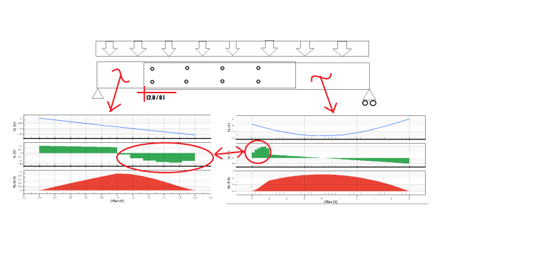
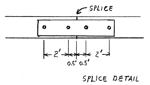
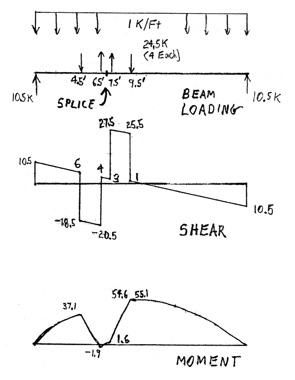
Wondering if anyone can point me to a method to analyze a beam lap splice (or however you want to call it) as shown in the image below. Looking to make a single, simple span beam, out of two lapped pieces of smaller length, (but identical cross sectional area, material) and secured together with bolts/nails/etc. I've ran a FEM model just to get a feel for what the shear and moment diagrams might look like thru the splice for the individual sections, but I cant reason out what's happening with the shear envelope. The only obvious thing is that the two portions of the graph circled in red, which correspond to the splice, add up to the expected shear values of a simple span beam over the splice. (The drawing above is just a crude concept and does not represent my actual model - sorry for the terrible resolution)

graphs_xoqike.png
 
Replies continue below

Recommended for you

The drawing above is just a crude concept and does not represent my actual model

Ok, so we can't help interpret the output with any certainty because we'd be guessing at what you've modelled. But what's the situation generally? Is it two beam lengths that are each half of the span, with a third piece splicing them? You say you're looking to make this out of two pieces so I'm not sure.

In the area of the splice, are you applying the load to the splice piece, the outer pieces, or both?

If the model is (supposed to be) symmetric but the results aren't, there's a model error. You could try making a symmetric model to check your method.

I think you could solve this with a few free body diagrams and assumption of the bolt behaviour, eg elastic distribution of load based on polar moment of the bolt group.
 
I think I understand now. One of the vertical lines at the end of the overlap is meant to be hidden detail, and the left piece is much shorter than the right piece. What I said above still applies in principle. The results will be affected by how you share the applied load in the overlap region.
 
Is your loading a simple distribution as graphically shown? Why not find [highlight #FCE94F][/highlight]the values by hand / using AISC tables and design spice for required shear and moment. If loads are relatively small, I just design splice connection for max shear and moment beam will see.
 
sturctee - The beam at the splice location can not resist moment. On both sides of splice location, the fasteners form couples; each couple resists moment equal to what would have been present in the beam at the splice location. The couple on each side of splice have opposite signs. Assume no friction between beam and splice plates. An example is clearer than words:

Assume a 21' long spliced beam with simple supports, supporting a UDL of 1 kip/ft. The splice is located 7' from the left end. Moment at the splice location is 49.0 kip-ft.

structee_-_Beam-600_umleac.png


For simplicity, the spice plates are connected to the beam with two fasteners on each side of the splice location.

structee_-_Splice_Detail-600_auzsvg.png


Each pair of fasteners form a couple resisting 49.0 kip-ft. Redraw the free body diagram with the UDL and the point loads on the beam where each of the four fasteners are located. Redraw the shear and moment diagrams for the beam. I made the semi-graphical solution shown below. Note that both the shear and moment diagrams resemble your illustration.

structee_-_Splice-600_gvg8xb.png


For the benefit of the discussion, the model whose results are in the original post is actually something like the image below.

SplicePlan_tw8ftj.gif
 
Status
Not open for further replies.

Part and Inventory Search

Sponsor