Continue to Site

Eng-Tips is the largest engineering community on the Internet

Intelligent Work Forums for Engineering Professionals

  • Congratulations KootK on being selected by the Eng-Tips community for having the most helpful posts in the forums last week. Way to Go!

Beam Deflections

Status
Not open for further replies.

SE2607

Structural
Sep 24, 2010
206
Still a RISA noobie.
I'm checking deflections of the attached model, particularly Span 2 of FB-1. When I look at the spreadsheet for Member Deflections (Explorer/Results/Member Deflections), I find the minimum (maximum negative) deflection to be 0.28" for LC 3.LC 3 is full LL (RLL + FLL). This in itself is a little surprising since I'm expecting more deflection with partial LL loading (LC 2). Regardless, when I look at a detailed report for Member 1, I see a minimum deflection of -0.413" for the envelope of LCs. Scrolling through the various LCs and it does show that the -0.413" is from LC3.

Question: Why is the deflection -0.413" in the detailed report but -0.28" in the spreadsheet?

Thank you,
 
Replies continue below

Recommended for you

It's possible you're looking at total global deflection for the 0.413" which account for support movement. And the 0.28" is the local deflection of the member.
 
FYI, you did not attach your model to the post.

I see one of two possibilities.
1) What Jayrod said. The member deflection results will tend to report the RELATIVE deflection of the beam compared to its end points. So, if the beam is simply supported between two girders each of which deflect 0.2" and the maximum deflection shown in the detail report was 0.4" at mid span, then the relative deflection would be something like (0.4-0.2= 0.2). Make sense?

2) The other possibility is that RISA can get confused over whether a beam is simply supported or cantilevered. If the deflected shape makes RISA think it's a cantilever (or vice versa) then it can report incorrect deflections.

Caveat: I haven't used RISA much in the last 3 or 4 years. So, it's possible RISA may have changed it's reporting a little since I left. Also, I am a former RISA employee who left with some not so pleasant feelings when it was bought out by Numetsheck and I now work for one of their competitors. Therefore, I am a somewhat biased participant on all subjects related to RISA.
 
Jayrod/Josh:
Thanks for your responses.

I guess I'm not only a RISA noobie, but a Eng-Tips noobie as well. I thought I had uploaded the file. Just tried again. Hopefully, this will work. If you get it, please compare "member deflections" in the results menu to the differences between deflections for the load combinations in the detailed report for member FB-1.

No cantilevers. Yes, I checked all the support designations under "Additional Properties".

I *don't think* it's an issue regarding relative vs. global deflections, but, if it were, that a LOT of deflection in a post or steel column. I just did a quick PL/AE for the heaviest loaded column and that result was 0.019".

 
 https://files.engineering.com/getfile.aspx?folder=cf5b6a53-724d-4e97-9c0c-a28349a96b4d&file=22310.r3d
Ahhh, I see much better now. Yes, this (I believe) a RISA reporting limitation. So, the member deflections spreadsheet doesn't know that the member has two spans. It's reporting the results as if there is just a single span. That's the 1st problem.

The 2nd problem is the member deflections spreadsheet is only reporting the deflection results at the 5 "reporting sections" of the beam. That means the two ends and the 3 quarter points of the beam. None of which come anywhere close to the location with the maximum deflection.

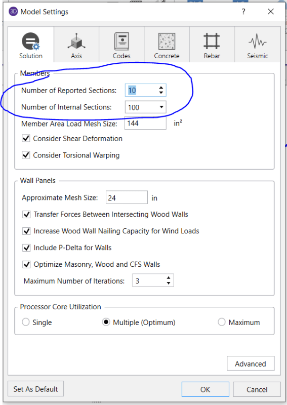
If you were to look at the Global Model Settings you would see that there are two settings on the Solution Tab for member sections. Number of Sections (for results spreadsheets) and Number of Internal Sections (for detail reports and code checks).

Honestly, a deflection check is close enough to a "code check" that RISA really shouldn't be reporting it this way in the spreadsheet results anymore. But, I won't comment further..... as the folks over there wouldn't appreciate my comments.

Model_Settings_xyzayy.png
 
Yeah, I'm aware of those settings. It didn't make much difference, in fact, none at all:
With 10 sections, max dl deflection is -0.255 @ x = 278.55 in
With 20 sections, max dl deflection is -0.255 @ x = 278.179 in
I realize this isn't 100 sections, but I can't imagine there would be much of a difference since there is none going from 10 to 20 sections.
Something must be up with what I'm expecting when I select "Member Deflections" under Explorer/Results/Member Deflections.
I'll query tech support and report my findings.
 
Break the member into two beams of 20 sections each. I think you'll see a difference then.

Keep in mind that the member deflections spreadsheet isn't reporting span 1 and span 2 results, right? At least it isn't in the version that I'm using (which is admittedly an older version). Therefore, the relative deflection reported by RISA is measured from a straight line draw from the deflected end points of that beam.
 
Josh -
Instead of breaking the member into two, I've changed the first three LCs to represent DL, LL and DL+LL deflections based on the BLCs. It turns out that the only thing the autogenerated LCs for deflections do is to establish LCs for "Suggested Designs", not to be compared with the Detailed Reports. From now on, I will check deflections based on the three LCs I've created for deflection checks and then look at member deflections based on Batch rather than Envelope mode.

I appreciate you taking the time to look into this for me.

Regards,
 
 https://files.engineering.com/getfile.aspx?folder=c2c574a2-b783-4b76-8f41-4dd9252376ed&file=22310.r3d
Status
Not open for further replies.

Part and Inventory Search

Sponsor