Continue to Site

Eng-Tips is the largest engineering community on the Internet

Intelligent Work Forums for Engineering Professionals

  • Congratulations waross on being selected by the Eng-Tips community for having the most helpful posts in the forums last week. Way to Go!

Beam Cover Plate Moment Splice Check 3

Status
Not open for further replies.

bookowski

Structural
Aug 29, 2010
983
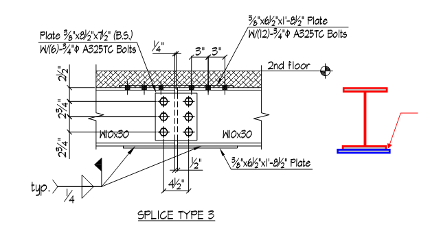
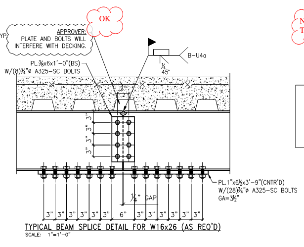
See attached. This is from a shop drawing, the detailer's proposed moment splice in a beam. He is doing bolted at the top flange and a welded cover plate at the bottom (due to clearance/height issues). The plate is wider than the beam, I'm guessing that this is to avoid overhead welding. He is not welding the end, only the sides.

When checking this I feel like there should be some kind of double shear lag check to get the force up to the connection plane and then out to the corners. Am I imagining this? Any special checks for this beyond the usual? Something about this rubs me the wrong way. I'd like to weld the end but that would force him to weld overhead or flip the beam once spliced.
 
 http://files.engineering.com/getfile.aspx?folder=ad893f98-da32-46ac-9f23-8e9542e22123&file=Mom_Conn_Shop_Dwg_-_Copy.png
Replies continue below

Recommended for you

Looks like something a fabricator would suggest.... not terrible. But, just different enough to make me uncomfortable.

I don't like mixing the bolts and welds like that. I feel like the stiffer welds will take a disproportionate amount of the force. Why not weld the top too? Then I'd be a lot more comfortable with it.

Not saying that it can't be done this way. Just that I don't like it.
 
Never thought about this situation before but here's my initial consideration:
Assuming they're not slip critical bolts, I think you'd have issues with mixing welds and bolts. Bolts need a little room to slip into bearing and the welded connection doesn't give you that. You'd get disproportionate force in the bottom flange until the bolts kick in. Maybe it can handle it, maybe not.

I would just have him weld the top and bottom. You can make the top plate narrower than the flange so it's all welded overhead. If you need to thicken it, lengthen it, or weld the ends of the top plates you can do so.

I don't believe you need a shear lag check because the length of your weld appears to be greater than 2x the width of the bottom flange. (I think this is Chapter D in AISC 360)
 
I have no problem at all with the proposed connection. KootK approved!

Book said:
When checking this I feel like there should be some kind of double shear lag check to get the force up to the connection plane and then out to the corners. Am I imagining this?

I'm not sure that I understand what you're proposing as the second stage lag issue here. Is it the vertical offset between the centroid of the flange plate and the centroid of the flange? If so, that's valid but would amount to next to nothing. I see this as straight up tension lag between flange and flange plate. Just the "out to the corners" bit.

JP said:
I don't like mixing the bolts and welds like that.

I don't share this sentiment. I essentially see the upper and lower flange connections as two independent connections, neither mixing bolts and weld. I might have concerns if this were a designated seismic hinge or a fatigue situation bit I don't think that's the case here. I'm guessing NY historic reno.

I like to debate structural engineering theory -- a lot. If I challenge you on something, know that I'm doing so because I respect your opinion enough to either change it or adopt it.
 
I don't know KootK, if we imagine this connection with really sloppy holes for the bolts, the bottom plate and welds would experience tension until the bolts finally went into a bearing condition. Now you'd have additional "initial" tension in the bottom plate/welds.

Then lets say the beam finally experiences it's design loads, will that plate or weld hold up if they were designed without that "initial" tension in mind?

That might be stretching it but this is what I'm envisioning at the moment.
 
I'm ok with the bolt/weld mix, especially since they're TC bolts. Something was just rubbing me wrong about the welding only at the extreme edges of the flange. I think I'm making it up though.
 
and KootK - for the double yes I was talking about the vertical and horizontal. For vertical it's the offset of the 1/2 the beam, the centroid of the WT section. Something like case 2 + case 4 in table d3.1 shear lag factors (13th edition). Even if I applied both factors it still works.
 
This isn't mixing bolts/welds in the way that those papers are referring to. It seems that the top and bottom flange can fairly be treated as independent for the most part. I see bolted bottom flange and cjp top flange field splices all the time, just never saw this configuration.
 
DETstru said:
I don't know KootK, if we imagine this connection with really sloppy holes for the bolts, the bottom plate and welds would experience tension until the bolts finally went into a bearing condition. Now you'd have additional "initial" tension in the bottom plate/welds.

As I see it, this scenario would violate statics. T_flange = C_flange ~ M/d. Always and no matter what, right?

SRE said:
The James F. Lincoln Welding Foundation appears to agree with JoshPlum and for the same reasons:

As best I can tell, none of those documents cover this particular case. Certainly, I agree that bolts and welds should not be used in concert to resist a common force. I still contend, however, that here the top flange and the bottom flange rationally represent two separate connections, neither mixing bolts and welds.

I like to debate structural engineering theory -- a lot. If I challenge you on something, know that I'm doing so because I respect your opinion enough to either change it or adopt it.
 
I agree with Koot on this....this is not your classic "mixing of welds and bolts"...being a moment connection, if there is any slip in the bolts, it would result in a very slight extra rotation....now, on the otherhand, if this was an axially loaded member,IMHO, it would qualify for the mixing of bolts and welds and I would not approve it...
 
KootK said:
As I see it, this scenario would violate statics. T_flange = C_flange ~ M/d. Always and no matter what, right?

Correct me if I'm wrong: It would not violate statics the same way a prestressed concrete beam does not violate statics. The plate is initially tensioned "before" it becomes part of the beam.


bookowski said:
especially since they're TC bolts.

TC bolts only give you a "snug tight" connection. The bolts must go into bearing before they provide any resistance. If this were a slip critical joint, I'd have no issue.
 
book said:
and KootK - for the double yes I was talking about the vertical and horizontal. For vertical it's the offset of the 1/2 the beam, the centroid of the WT section. Something like case 2 + case 4 in table d3.1 shear lag factors (13th edition).

Well yes, if you are looking to develop the plastic moment capacity of the entire section including the web, then I would agree 100%. Based on the proportions of the detail, I was assuming that you were developing tension and compression forces less than bf x tf x Fy.

I like to debate structural engineering theory -- a lot. If I challenge you on something, know that I'm doing so because I respect your opinion enough to either change it or adopt it.
 
DETstru said:
Correct me if I'm wrong: It would not violate statics the same way a prestressed concrete beam does not violate statics. The plate is initially tensioned "before" it becomes part of the beam.

I'm afraid that I just don't see it DETstru. If you FBD through the centre of the splice under an applied moment, I see no way for the tension and compression forces not to be equal. Even if you used longitudinally short slotted holes in the top flange, this should still be the case. Granted, bookowski wouldn't much like the deflection...

Book said:
I see bolted bottom flange and cjp top flange field splices all the time, just never saw this configuration.

I forgot to ask, what scenario leads to this detail? I've yet to encounter it. Perhaps the CJP is less disruptive to the deck above?

I like to debate structural engineering theory -- a lot. If I challenge you on something, know that I'm doing so because I respect your opinion enough to either change it or adopt it.
 
Correct, not developing the full moment capacity. Just trying to think through the load path and how this works in general. I think that for my loads/condition it easily works.

DET - I don't the see bolt/weld issue here. The flanges each must carry T/C and be in equilibrium. Where is the C offsetting the initial T, unless you are thinking of the interaction of the web initially, or some catenary/hanging action initially?
 
It's not the classic example of mixing bolts and welds as KootK says. But, it's still outside my comfort zone. That's why I said that it looks like something a fabricator would suggest!!

Overall, there isn't anything that makes me say, "no way, this is flat out wrong". Especially if they're using slip critical bolts.

In that sense, I agree with KootK and the others. But, at the same time, I wouldn't put my stamp on this connection unless there is a compelling reason for them to resist welding both the top and bottom flanges. Not sure what the difference in cost would be...

 
book said:
DET - I don't the see bolt/weld issue here. The flanges each must carry T/C and be in equilibrium. Where is the C offsetting the initial T, unless you are thinking of the interaction of the web initially, or some catenary/hanging action initially?

I suppose that you might get some flexure in the lower plate prior to bolt engagement. At ultimate, you'd still be able to plastify the entire plate in tension however.


I like to debate structural engineering theory -- a lot. If I challenge you on something, know that I'm doing so because I respect your opinion enough to either change it or adopt it.
 
KootK - See attached, yes it's to avoid clearing for the deck. The detailer here is putting this note because we showed an all bolted splice. Surprising it's worth it but I've seen it a lot. In general all of those 'tips for an efficient steel building' never seem to apply to what I see.
 
 http://files.engineering.com/getfile.aspx?folder=780334aa-3871-41f0-8a9b-d609c7cf17fe&file=CJP_and_Bolted_MC_-_Copy.png
The classic example of bolts and welds is where they share the same tension force. The problem with that is that the welds are so much stiffer that the entire tension goes into weld. The bolts are so flexible that they won't really take any load until the weld begins to fail. In this example, there is no direct sharing of tension. So, not as much of a concern. I can certainly see that.

However, there is still a strain compatibility issue. The connection will deform more at the top before the bolts engage. You'll get movement at the top, but little movement at the bottom. My feeling is that this will put more stress on the weld, though I don't know exactly how. Because I don't know exactly how it will work, I'm a bit uncomfortable with it.

I keep thinking back on the pre-Northridge connections where they found the flange welds were taking the shear forces because they were more rigid than the bolted shear tabs that were assumed to take all the shear. Not exactly the same situation here. But, similar enough to raise some concerns. I'm confident that (at least at seismic level loads) we couldn't get this connection anywhere near the probably plastic moment of the beam.

That's probably too stringent of a criteria to use for the OP's project, of course. And, for lower moment demand and less ductile requirements, it would likely be fine..... just not with my seal.
 
FWIW - AISC suggested details (9th Ed.) for bolted moment splices have a small gap between the ends of the beams.
For welded moment splices, both flanges webs of the beams are butted together.

In the original illustration there is a gap at the bolted flange, the bolted web, and the welded flange.

Mom_Conn_Shop_Dwg_-_Copy_ayuxpc.png


In the second illustration there is a gap at the bolted flange and the bolted web, but not at the welded flange.

CJP_and_Bolted_MC_-_Copy_hplvtg.png


[idea]
[r2d2]
 
Status
Not open for further replies.

Part and Inventory Search

Sponsor