Tek-Tips is the largest IT community on the Internet today!

Members share and learn making Tek-Tips Forums the best source of peer-reviewed technical information on the Internet!

  • Congratulations cowski on being selected by the Eng-Tips community for having the most helpful posts in the forums last week. Way to Go!

Base Shear and Period Question: Response Spectrum Analysis vs. ELF

Status
Not open for further replies.

Respawn

Structural
Joined
Sep 28, 2020
Messages
76
Location
US
I did a response spectrum modal analysis on a 5 story RC Special moment frame parking structure on SAP 2000. I am concerned about my results when comparing to my Equivalent Lateral force procedure results. The response spectrum defined was IBC 12. Additionally, I checked to ensure units are consistent throughout.

Base Shear:
- ELF= 4429.7891 Kips (Both Directions)
- RS = 7050.04 k (X- dir, global)
= 90358.57 k (y dir, global)

Periods:
- ELF: Ta= 0.64 s ----> T= Ta*Cu = 0.64*1.4= 0.9s
- Modal: T = 1.41s

Is there any way to bring my base shears down on the model? Additionally, is there a way to bring my period up on the response spectrum curve?
 
OP said:
ELF: Ta= 0.64 s - Modal: T = 1.41s
Which method are you using to determine the time period for equivalent procedure? If you use the option to calculate time period by program, then both modal and ELF should give the same time period for modes contributing majorly in X or Y direction.

OP said:
ELF= 4429.7891 Kips (Both Directions)
Okay! This is some serious base shear. Not to mention in a high seismic region. Forget the Response spectrum, first investigate why the structure is attracting such high base shear. Closely look at the mass and stiffness inputs. A stiff structure is more likely to fail even at small deformation. Design methodology of seismic is based on the fact the structure is ductile enough to dissipate energy. Give the structure some room to deform.
 
What's the mass participation for the mode with 1.41 seconds?

Is there a lot of torsion in the model? This can cause some confusion in the signage of various reactions, leading to larger reported base shears.

Are there lateral supports at more than one level? This can throw off the base shear calculation.
 
@JoshPlumSE

The mass participation per load is attached. There was not a lot of torsion. Additionally, I am not sure what you mean by lateral supports at more than one level. Basically the model consists of 4 stories plus a roof that acts as level 6. A ramp is modeled as a shell element. The ramp is a single threaded helix leading to the roof. Then all beams and columns are modeled with cracked sectional properties. Lastly is a 5 in PT slab per floor.
 
 https://files.engineering.com/getfile.aspx?folder=a5d75e6f-a8d2-4566-bdef-416de1a99b9f&file=mass_ratios.PNG
In light of the picture of the model you shared, I take back my comment regarding the high base shear from ELF. Its apparent that the high base shear is due to the size of your model rather than stiffness as I presumed. Which, also seem to be more on the flexible side rather than stiff side.

Base Shear:
- ELF: V = 4429.7891 Kips (Both Directions), T= Ta*Cu = 0.64*1.4= 0.9s
- Modal: V = 90358.57 k (y dir, global) T = 1.41s

Logically, the above results do not make sense.
The higher the period, the less should be the base shear. If from modal analysis you are getting a high period than ELF, then the resulting base shear should be less than that of ELF.
Are you sure, you are using the right scale factor i.e. "Ig/R"? Make sure the units of g are consistent with the units of your structure model.

The mass participation per load is attached. There was not a lot of torsion.]
image_cujcev.png
 
What is your total seismic mass? Something seems fundamentally wrong here.
 
Yes, that does answer a lot of questions. You've got a pure torsional mode that seems to be dominating the behavior. Some quick thoughts:

1) You definitely need to solve for more modes. I'd recommend at least 5, probably more like 10 modes. I want to get the mass participation up to 90 percent in the X and Y directions. You'll probably need at least 2 modes per direction to accomplish this.

2) I'd take a real close look at the torsional mode. It seems odd based on what I've seen of your structure. I wonder if something is not modeled correctly.

 
Looking at your second attachment, I noticed that the display is set to deformed shape for dead load. It looks like slab is not meshed at all. Beams are deflecting independently from shell. Also, what are those grey areas at the periphery? have you modeled the parapet walls too?
 
@Blackstar123 Thank you for your feedback The grey areas are the barrier walls. The shell was constrained to the beam column joints. It was semi rigid, two way.

@JoshPlumSE Thank You!
 
Could you post the shape of first three modes?
With ten modes you activated enough mass, but torsion in second mode is not ideal.
 
I do not see any obvious errors in this model, maybe someone else might see them (I hoped the mode shapes would discover the error).
However, I'm wondering if barrier walls really do provide a fixed connection to the column. I'm not really sure how they are usually detailed and constructed (is there a gap between the column and the wall?).
 
OP said:
The shell was constrained to the beam column joints. It was semi rigid, two way.
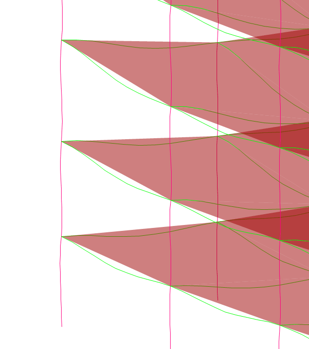
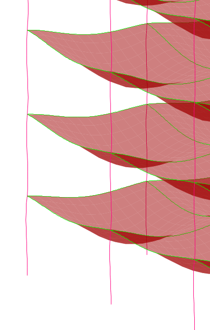
Okay, but have you at least assigned an auto mesh property? Because from the deformed shape, it doesn't appear to be meshed at all.

Do you see the difference between the deformation of a meshed and no meshed slab in the pictures attached below? Beam and slab are deforming independent of each other in the first one. What do you thin which behavior is close to the reality? If you do not meshed a shell element, any load on the area will go directly to the points supporting its 4 nodes rather than following the intended path i.e. shell to beams to columns to foundations.

image_bukvxv.png


image_g845ap.png


OP said:
The grey areas are the barrier walls]
I think as per ASCE requirement, barrier walls should be design to resist a horizontal load of a certain magnitude, which also, should have a clear load path to the supporting slab or beam.
If the wall will be cast in second stage, I would assign its load on supporting frame instead of modelling it as a shell. As for laterally restraining the barrier wall on columns, I am not sure what I would do. I'll need to do a little bit of research on the barrier wall, before I decide. Although, if you provide a snug tight connection with the frame, it will surely increase the shear demand on periphery columns than the other columns in the story.

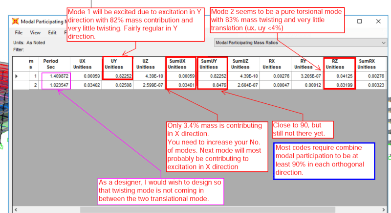
As for your mode shapes, you need to increase the torsional stiffness of your structure to kick the pure twisting mode out of the midst of the pure translational mode shapes.

One more thing the time period of mode shape 2 and 3 are too close for my liking. Not a good idea to have the peak response of two major contributing mode shapes so close to each other. During an earthquake, ground shaking change directions rapidly in violent upward downward forward backward motion. Just imagine your structure resonating at the frequency of mode 2 when ground motion switches gear and direction and now it start resonating translationally while your building was still trying to regain its footing from twisting motion.
 
Status
Not open for further replies.

Part and Inventory Search

Sponsor

Back
Top