Continue to Site

Eng-Tips is the largest engineering community on the Internet

Intelligent Work Forums for Engineering Professionals

  • Congratulations waross on being selected by the Eng-Tips community for having the most helpful posts in the forums last week. Way to Go!

Balustrade moment on I-Steel beam 1

Status
Not open for further replies.

Redtelis

Structural
Jan 18, 2019
47
Hi,

What check would you normally carry out to a steel I-Section beam when a balustrade will be fixed to the side of a steel beam web?
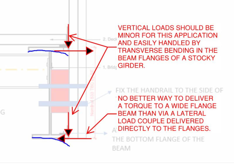
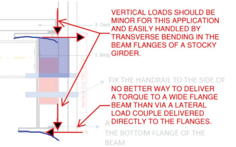
Obviously, the applied horizontal load to the balustrade will transform a moment to the steel beam. Is this a torsion check of the beam maybe? From my understanding, as the balustrade bottom fixing is connected to the side of the i-section beam (web), it will try to rotate it. On the other hand, the floor plate is a steel mesh with diagonal horizontal bracing to tie and restrain the I-Section beams. Can we argue that the applied moment will be resisted by the diagonal bracing?

Thanks
 
Replies continue below

Recommended for you

OP said:
Can we argue that the applied moment will be resisted by the diagonal bracing?

Normally no but it's difficult to say for sure without seeing your details and framing configuration. In many instances, the beam torsion will be resisted at close intervals by perpendicular framing or kickers. With that in play, it's mostly an exercise of ensuring that the various connections can transmit the bending moment coming out of your balustrade to macroscopic torsion in the beams.
 
generally tie it back to the floor structure to minimise torsion.

Rather than think climate change and the corona virus as science, think of it as the wrath of God. Feel any better?

-Dik
 
As above. It depends on a bunch of factors including span and the twist restrint. If you have ties of either from flooring perpendicular framing or even a 90 degree corner on your handrail to your balustrade then that should be sufficient. But if you lack twist restraint then an the torsion that a handrail can impart on a beam can be significant.

I must admit I made a design mistake on this matter a couple years ago. It was a 5m span with 150mm deep channel and no tying members, flooring was clamped grating which is not an effective tie. Thus the only resistance to torsion was the channel. The deflection on the handrail (~75mm on a moderate push) was outside of code and wasn't confidence inspiring though strength wasn't a concern. The onsite fix was a simple 30minute job connecting the handrail to another panel of handrail that ran perpendicular.

Redtelis said:
On the other hand, the floor plate is a steel mesh with diagonal horizontal bracing to tie and restrain the I-Section beams.
If the mesh is welded then it might offer some resistance but you are only restraining the top flange with the bottom able to rotate. Likewise with the diagonal members their ability to provide twist restraint is dependent on a multitude of factors.

generally tie it back to the floor structure to minimise torsion. said:
generally tie it back to the floor structure to minimise torsion.
In many cases the floor structure might not provide sufficient torsion restraint.


But we are all just guess in the dark hear at the actual scenario. A decent picture/drawing is worth a thousand words.
 
Hi,

Thanks for your answers guys.

Here is a screenshot of a typical section. I am not going to design the handrail posts or fixings but I have to comment on the design intention. The architect shows fixings to the top and bottom flange with angles, I don't think that this is a sufficient bottom fixing connection as it transfer the loads just at one side of the flange. I show with a sketch that the balustrade panel needs to be fixed to the side of the beam web.

Any comments will be much appreciated.

ps. the horizontal bracing span from side beam to side beam. I just noticed in the upload sketch that this is not shown!
 
 https://files.engineering.com/getfile.aspx?folder=fac488a8-f969-4d5d-8d8a-a6675e60b7a3&file=H1.PNG
Without a plan detail we don't get enough of a picture. But it looks like there is nothing to worry about.

That secondary beam looks likely to provide sufficient stiffness. Not to mention the size of the primary beams should mean decent torsion resistance. How about you just run the calculation? It shouldn't be that hard. Deflection should be your primary criteria.

I design lightweight walkway gantries all the time. The torsion from handrail is rarely something that is an issue. Generally perpendicular secondary beams will provide enough torsional stiffness. For short spans the end restraints provide enough stiffness.
 
@Human909

Yes, its probably worth checking the torsion resistance of the beam.

Just to give an idea of the structure: It is a steel footbridge, simply supported one span 12m. The main edge beams are to be relatively very stiff sections (probably 533UB's). The secondary beams are to support the steel mesh decking.

To be fair, if it was another structure, I wouldn't be worry too much but because I have neve designed a footbridge before, I want to make sure that even the small details will not create any issues to the main structure. I also need to start checking thermal loads and vibration analysis which is probably another question to the forum haha!
 
533UB is pretty hefty for a 12m span. So is this being designed for the possibility of densely packed crowds? If so then you could get much higher pressures on the balustrade than regular design requirements. So it might worthwhile checking it. Adding torsional restraint at mid span doesn't cost much and could vastly improve things. All you need is a full depth diaphragm member or a single diagonal strut to the bottom flange.

Like I said I've been designing things like this for years. But my loads are equipment and only 2.5kPa pedestrian load. Which essentially a 0% probability scenario for these walkways. If this is something like a public pedestrian footbridge then then consideration of the crowd loads is obviously vital.

Here is one example that is memorable for me. This was meant to be a 'temporary structure'. However they didn't allow for crowds which should been very much expected.
 
Top flange:
This is restrained by the horizontal in my view (which is part of the bracing system)

Bottom Flange:
Why not just do a small diagonal fly brace from bottom flange to the horizontal member. This horizontal member presumably being part of the bracing which resolves the force.
 
Just my take... The W section could be coped and raised to U/S of deck and tubes could be eliminated (helps with stiffness). I don't know what the spacing of the beams are. Deck is spanning the wrong way to stiffen floor and guardrails. Connection plate (if that's what it is) should be raised to be in line with beam flange to minimise moment on post and to provide more stiffness... Deck should bear on beam flange, not angle... maybe a thicker deck or topping to eliminate the X-bracing... other than that looks OK. Are the clip angles top and bottom to support guardrail post? 12m span may be prone to some vibration if lots of people...

Rather than think climate change and the corona virus as science, think of it as the wrath of God. Feel any better?

-Dik
 
OP said:
The architect shows fixings to the top and bottom flange with angles, I don't think that this is a sufficient bottom fixing connection as it transfer the loads just at one side of the flange.

I feel that the architect's proposal has merit. See the sketch below. The architect's proposal also may be advantageous in that it separates the guardrail and infill beam connections such that you'd never have to worry about one of them interfering with the other if the spacings are not coordinated.

C01_cmy8qa.jpg
 
I like to connect the balustrade to the web, but on a full/partial depth stiffener, instead of your detail. The angles can be eliminated too.
 
Better to connect directly through the web and line up with smaller beams, and no torque transferred to the large W sections...

image_vzrltk.png


Rather than think climate change and the corona virus as science, think of it as the wrath of God. Feel any better?

-Dik
 
dik said:
Better to connect directly through the web and line up with smaller beams, and no torque transferred to the large W sections...

Yes, it's better structurally but only if the stanchions actually line up with the infill beams. Generally, I'd not assume that to be the case. This is precisely what I was speaking to previously with this statement.

KootK said:
The architect's proposal also may be advantageous in that it separates the guardrail and infill beam connections such that you'd never have to worry about one of them interfering with the other if the spacings are not coordinated.
 
It is in sense of shear delivering, web connection is more stable than tip of flanges.
 
Right, but as I mentioned in my previous post, the shear demand will be negligible and it is the moment demand that is critical. In strategically designing the connection, we need to remain cognizant of the particular application.
 
It may well be that the upper angle is needed as some kind of kick plate anyhow. If so, we might as well use it for supporting the guard.
 

That's the way I build them... then they line up... If not, it's still easier to accommodate torsion and the span for the deck may be 5' or 6' or 10' with 3" deck... too many ifs... and deck support can be C sections and the plate still works...

Rather than think climate change and the corona virus as science, think of it as the wrath of God. Feel any better?

-Dik
 
1) I'm pretty sure that this is bar grate deck application, not corrugated steel and concrete. So your infill beams are unlikely to be spaced at 10'.

2) If the proposed stanchion stiffeners don't line up with the infill beams then they won't help meaningfully with beam torsion. That they might is a common misconception.
 
Status
Not open for further replies.

Part and Inventory Search

Sponsor