Okay, Karthik, with my newfound knowledge I can conjecture what an inerter built around a ballscrew might look like:
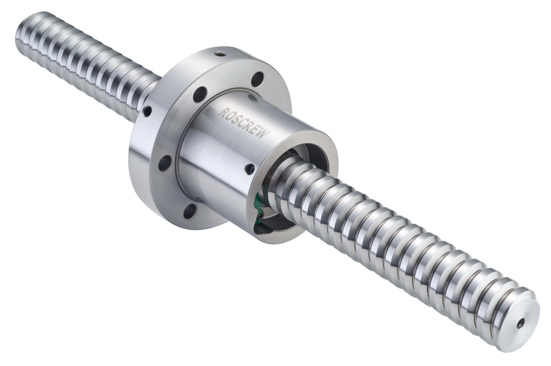
It might comprise a ballscrew assembly with the ball nut attached firmly to a heavy mass, which is free to rotate inside a shell, and free to rotate relative to the shell, thanks to a sturdy thrust bearing which transfers axial loads to a bulkhead within the shell.
The shell and one end of the ballscrew are coupled to two objects that move relative to each other, so that the ballscrew translates in and out of the shell, just like the rod of a shock absorber, and the ball screw is prevented from rotating by its attachment to the external mechanism, and the shell is similarly coupled to the external structure and prevented from rotating.
I.e., the ballscrew is used in reverse from the the usual situation, where instead of the nut rotating and driving the screw, the screw translates linearly and drives the nut in rotation.
... but you seem to be talking about a different arrangement, where the screw rotates as part of its primary function.
Do you have a drawing of the mechanism about which you are speaking?
Mike Halloran
Pembroke Pines, FL, USA