Continue to Site

Eng-Tips is the largest engineering community on the Internet

Intelligent Work Forums for Engineering Professionals

  • Congratulations cowski on being selected by the Eng-Tips community for having the most helpful posts in the forums last week. Way to Go!

ASME Y14.5 technical question

Status
Not open for further replies.

ANGIDDT

Automotive
Sep 14, 2019
3
TB_uyrbfk.jpg


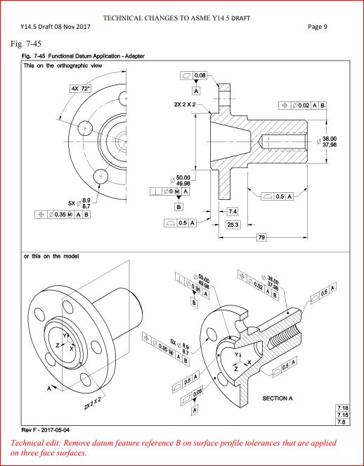
ASME Y14.5-2009 figure 4-38 has "B" as secondary in the profile callout for the planar surfaces (three face surfaces)
The new version 2018 of the same standard removed "B" intentionally -- as clearly shown in the technical changes draft --document attached.

Does anyone of the members of this forum (maybe committee members or just GDT passionate) have some ideas on why this change has been done?
What could be a good reason?

Does not look like just a clerical change/ mistake/ typo or an unintentional change... ( as 2x 2 x 2 for the end face chamfer instead of 2x 2X45° probably is)

Any input will be greatly appreciated.
 
Replies continue below

Recommended for you

I would venture that it's because a secondary datum B has no relationship to those three surfaces. They are related to datum A by location and orientation, but datum B only centers the part axially. Thus it added no value to the profile callouts.


John-Paul Belanger
Certified Sr. GD&T Professional
Geometric Learning Systems
 
The reference to in the '2009 profile callout would have enforced a simultaneous requirement with the other tolerances such that if datum feature [A] was not flat any of the multiple candidates would be used for all the evaluations. With that restriction removed then a different candidate for datum feature [A] can be used for the profile than is used for the other features.

(The reason for the removal should have been specified in detail as to why it was important and the exact reason it makes a difference. That's not how this process works; someone gets an idea about some change they want and makes an in-person argument and any reason is just what is appealing at the moment with no accountability.)
 
3DDave said:
The reference to in the '2009 profile callout would have enforced a simultaneous requirement with the other tolerances such that if datum feature [A] was not flat any of the multiple candidates would be used for all the evaluations. With that restriction removed then a different candidate for datum feature [A] can be used for the profile than is used for the other features.


Which is no longer the case in 2018, thus the decision to remove B from the profile callouts.
 
The candidate datum concept.

With a single solution as default, there is no multiple candidates for A any more.
 
How is that enforced across multiple setups? Seems like the CMM guys won this round.
 
My assumption is that it wouldn't be "enforced" across multiple setups but that each setup would choose the candidate datum which best satisfies the single solution (minimum separation) requirement in 2018.

This would theoretically result in the same solution, except for small differences in each setup. I have to wonder whether there could be a geometry which would have more than one possible solution which equally satisfy the minimum separation requirement - my instinct says no.
 
The differences between the two procedures (candidate datum set -default in 2009- versus single solution to minimize the separation -default in 2018 - has been discussed (at least tangentially) here:

Two quotes from experts (Evan J) might be helpful (I personally like these explanations)

" The new stabilization default for RMB datum features will have some impact, but I'm not sure how much. I suppose that this depends on how often candidate datums on a rocking primary datum feature actually come into play. How often do you see a part rocked to an optimal orientation on a surface plate during inspection? I haven't seen that very much. When a part is CMM inspected, the software rarely/never tries different candidate primary datum planes."

"With the new default of a single solution that minimizes the separation between the feature and the true geometric counterpart, the inspector is no longer allowed to wiggle the part on the gage. How the inspector knows that the proper single solution has been achieved is another question entirely. There are definitely some practical implications (unintended consequences?) associated with the new default - these are going to be discussed and debated for the next few years, I'm sure. "
 
How often do you see a part rocked to an optimal orientation on a surface plate during inspection? I haven't seen that very much. When a part is CMM inspected, the software rarely/never tries different candidate primary datum planes

How the inspector knows that the proper single solution has been achieved is another question entirely. There are definitely some practical implications (unintended consequences?) associated with the new default

Hmm the more I think about this the more problematic it becomes. So if the datum feature itself is being probed and the datum plane is being established virtually then likely nothing much changes from current practice - it makes sense that the software would choose the single solution which minimizes separation by default. Whether most software isn't setup to attempt to choose other candidate datum planes if the feature(s) don't pass I don't know.

However if it is instead being put on a surface plate or other gauging surface instead of being directly probed, I wonder how it is expected that the inspector guarantees the proper single solution has been achieved. I would say probably without directly probing the datum feature it would be difficult and time consuming.

Evan says "How often do you see a part rocked to an optimal orientation on a surface plate during inspection?" and he's probably right that its not a regular occurrence, but at the same time how do we know however it was set on the surface plate is the "single solution"? At least per 2009 it was not difficult to be reasonably sure that it represented a valid candidate datum - now according to the letter of the standard in 2018 there is only one correct orientation.
 
My assumption is that it wouldn't be "enforced" across multiple setups but that each setup would choose the candidate datum which best satisfies the single solution (minimum separation) requirement in 2018.

Does ASME Y14.5-2018 say something like "single solution that minimizes separation between datum feature and simulator"? Does it clarify whether the separation to be minimized is the maximum separation (distance) at any single location, the total separation (volume) over the entire feature, or perhaps something else?


This would theoretically result in the same solution, except for small differences in each setup. I have to wonder whether there could be a geometry which would have more than one possible solution which equally satisfy the minimum separation requirement - my instinct says no.

Your instinct is basically correct, but that answer isn't terribly relevant when measurement uncertainty is considered. It's possible to have multiple candidates which are significantly different but appear to satisfy the minimum separation requirement similarly well. This uncertainty from the datum feature propagates through to the measured values for the tolerances that reference it.


So if the datum feature itself is being probed and the datum plane is being established virtually then likely nothing much changes from current practice - it makes sense that the software would choose the single solution which minimizes separation by default.

I know that one popular product uses a constrained least-squares fit by default, and I imagine that deviations from this default are fairly uncommon. I don't know specifics about other products, but I bet approaches based on least-squares are pretty popular.


pylfrm
 
Does it clarify whether the separation to be minimized is the maximum separation (distance) at any single location, the total separation (volume) over the entire feature, or perhaps something else?

No, of course you're right it doesn't. As with many things, Y14.5 specifies something which looks intuitive enough on the surface (see definition of local size) which is actually ambiguous. The actual text reads: "the default requirement is that the part be adjusted to a single solution that minimizes the separation between the feature and the true geometric counterpart per ASME Y14.5.1M" - pointing us to Y14.5.1 which only specifies a method to determine the candidate datum set, not to evaluate the new "minimum separation" requirement.

So now in addition to being, in my mind, problematic from a practical standpoint for the reasons I previously stated (ie: without direct probing of the datum feature or some other time consuming stabilization/orientation procedure) we now have a specification which is ambiguous in what exactly it means by "minimum separation." As I often find myself wondering, I question what exactly the committee was thinking when adding this requirement.

Your instinct is basically correct, but that answer isn't terribly relevant when measurement uncertainty is considered. It's possible to have multiple candidates which are significantly different but appear to satisfy the minimum separation requirement similarly well. This uncertainty from the datum feature propagates through to the measured values for the tolerances that reference it.

This seems to be a recurring theme whenever the standard tries to confine the outcome to a single solution - I think you've mentioned something similar when discussing evaluation of the UAME.

I guess add this to the list of reasons above why this new requirement might be problematic.
 
I found this on the www


copy-paste

"THE MOST NOTABLE CHANGE

The Default Stabilization for Datums

The biggest change in the standard relates to the establishment of a datum from a datum feature that is unstable (i.e. a convex surface “that rocks”). This applies to a planar datum feature or a datum feature of size referenced at RMB. In previous versions of Y14.5, the standard used the candidate datum set to derive multiple permissible datums (find the datum that works). The 2018 version is now using a default stabilized single solution: “the part is to be adjusted to a single solution that minimizes the separation between the feature and the true geometric counterpart”. This can be done with shims on a surface plate or with an official algorithm further outlined in ASME Y14.5.1 Mathematical Definitions of Dimensioning and Tolerancing Principles to be released at the end of 2019. This default stabilization algorithm is officially called the Constrained Least Squares. This will probably have the biggest impact to industry as CMMs and other digital metrology equipment implement this new algorithm. To be honest, the candidate datum set outlined in previous versions of Y14.5 was not used in the digital equipment without the use of hard fixturing. Digitally creating a datum from an imperfect datum feature has always been a difficult problem and each CMM software programmer had their own best solution. The Y14.5-2018 has certainly helped clarify with a single stabilized solution for the digital inspection frontier. It also helps reduce tolerance stacks from form and orientation variations on datum features."

There is even a picture for better explanation


Authored by:
Scott Neumann, Partner and Chief Engineer at TCI
 
article said:
This can be done with shims on a surface plate

This is along the lines of what I was thinking. I doubt thought that one can be 100% confident that the orientation established with this method conforms to a constrained least squares fit though (not to mention repeatability across multiple setups), and this would certainly increase setup and inspection times when coming across an RMB datum feature which has convex error (ie: rocks) when not directly probing the datum feature.

article said:
or with an official algorithm further outlined in ASME Y14.5.1 Mathematical Definitions of Dimensioning and Tolerancing Principles to be released at the end of 2019

I'll have to check my draft to see if this was included. At least this would clear up exactly what method is to be utilized.

article said:
To be honest, the candidate datum set outlined in previous versions of Y14.5 was not used in the digital equipment without the use of hard fixturing. Digitally creating a datum from an imperfect datum feature has always been a difficult problem and each CMM software programmer had their own best solution.

I don't get the "it was never really used" argument. Previously as long as the method chosen utilized a valid candidate datum then it was still conforming (actually that would mean technically it WAS used). It seems to me the new requirement has made the use of hard gauging/fixturing more difficult.

 
For what its worth, I read the Y14.5.1-20xx draft I have - it specifically describes a Constrained Least Squares fit to be utilized for a single solution requirement.
 
pylfrm,

Could you perhaps help me envision a case of when the below would apply? I'm having difficulty envisioning this for a planar feature.

It's possible to have multiple candidates which are significantly different but appear to satisfy the minimum separation requirement similarly well. This uncertainty from the datum feature propagates through to the measured values for the tolerances that reference it.
 
chez311,

Consider the following case:

Separation to be minimized is the maximum distance at any single location.
Datum feature simulator is the z = 0 plane.
Material of datum feature must be on the z > 0 side of the simulator.
Datum feature is composed of the following five points:[pre]
p1: ( 0, 1, 0)
p2: ( 0, -1, 0)
p3: (-1, 0, 0.01)
p4: ( 1, 0, 0.01)
p5: (-0.0001, 0, 0.03)[/pre]

Solutions where p1 and p2 both contact the simulator all have separation equal within 0.000003, but vary in orientation by about 20 mrad.


pylfrm
 
Status
Not open for further replies.

Part and Inventory Search

Sponsor