Continue to Site

Eng-Tips is the largest engineering community on the Internet

Intelligent Work Forums for Engineering Professionals

  • Congratulations 3DDave on being selected by the Eng-Tips community for having the most helpful posts in the forums last week. Way to Go!

Asking for help making sense of a grounding transformer

bdn2004

Electrical
Jan 27, 2007
806
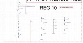
Below is a part of an EasyPower model showing a grounding transformer at the first switchgear coming off the large 100 MVA transformer that feeds this Plant. The grounding transformer is 500 kVA, 15kV Wye impedance grounded - 480 delta. Z= 4.87 ohms.
It has a 29 ohm resistor, 300A, 10 sec.

New to this type of installation.... thus the question.

I understand the resistor was sized Ohms law.... R = Vln/I = 8660/300 = 29 ohms. So changing the kVA value or the impedance of the transformer is not effecting the size of the resistor. And I've read the maximum current that could be in the ground circuit then is 300A. As I play around with this upsizing the transformer and lowering the impedance - it appears the number converges to 100A. Which I deduce would mean the 300A = Ia + Ib = Ic .... 300A? But why is that ... Since it uses Voltage to Neutral ? And if you have a 2 or 3 phases to ground... that's a phase to phase fault with high amps. Where would you ever see 300 amps ?

Note on this, there's more ground fault current at a fault at the grounding transformer coming down from the primary side solidly grounded wye connection of the Utility transformer than coming up through the grounding transformer
Grounding xfmr Screenshot 2025-06-11 102239.jpg
 
Replies continue below

Recommended for you

The ground fault current through the grounding resistor is basically the line-to-ground voltage divided by the resistance. The size of the transformer doesn't really impact the magnitude of the ground current much for low-resistance or high-resistance grounding.

You can switch EasyPower to display the sequence currents - this might be more useful in understanding what is happening.
 
3 x 100A zero sequence (in phase) which sum in the neutral to give 300A through the resistor.
 
Your wye is on the 15kV system.
The line to neutral voltage will be 8660 Volts.
That is the maximum voltage that the resistor will see during a line to ground fault.
8660 Volts / 29 Ohms = 299 Amps
Then we have a wrong understanding of some misapplied information.
The 299 Amps (Close enough to 300 Amps?) appears as a load on one phase of the primary supply.

But delta configurations are not always simple.
500 KVA / Root 3 = 290 KVA
290 KVA / 480 Volts = 600 Amps.
But, a 300 Amp current in one primary phase translates to a 5000 Amp current in the secondary.
That secondary current is a circulating current that circulates in all three windings and draws current from the unfaulted phases.
The Z is three times. The Amps are 1/3.
To make it more interesting, this will be less than the ASCC and so will be at an as yet unknown phase angle.

So, the actual voltage applied to the 29 Ohm resistor will be slightly less than 480 Volts due to voltage drop in the transformer winding.
How much less?
Not much.
The winding voltage drop will be highly reactive and the resistor voltage drop will be at unity.
The resulting voltage drop will be much less than may be suggested by a simple arithmetic addition.

Bottom line:
The value of 300 Amps is close enough for all practical purposes.
Any error is conservative on the safe side.

Transformer sizing:
Model the transformer as a delta:wye with a line to ground fault on one phase,
Compare the ASCC with the expected delta current when used as a grounding transformer.
You may adjust the KVA value or the resistor value to get the delta grounding current below the ASCC.
 
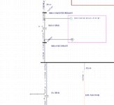
I still don't understand this ... I attempted to do what I think you are saying. I changed the 500kVA transformer to a Delta-Wye, changed the impedance to Z=3.85 and which yields 300A in the primary on a phase to ground fault at the secondary terminal of the 500kVA transformer. So that's the max ground current with the 29 ohm resistor, per the discussion. The question I'm trying to answer... There is a ground relay on the feeder breaker that is set at 150A. Is that value reasonable ? I'd like to see it modeled to prove it.

Grounding xfmr.jpg
 
You want the relay to pick up om a ground fault.
The 300 Amp current represents a bolted fault, the worst case.
In the real world a bolted fault is unlikely.
Actual fault current will normally be less than the worst case bolted fault.
Consider the case of a feeder shorting to an equipment enclosure that is protected by an equipment grounding conductor.
Now the resistance limiting the fault current is the 29 Ohm resistor in series with the impedance of the feeder conductor plus the impedance of the equipment grounding conductor.
In the case of a long feeder to a smaller motor, the fault current may even be less than 150 Amps.
Where to set the relay pick-up?
It depends.
 

Part and Inventory Search

Sponsor