BulbTheBuilder
Structural
I need help understanding this and correct me if I am wrong. I have been trying to get deeper understanding of wind loading in ASCE 7-16.
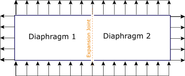
When wind blows, we have the windward, leeward, and vortex (at the side of a structure). Is that what Figure 27.3-1 is trying to illustrate? From the image we can see the wind spreading perpendicularly to the wind direction.
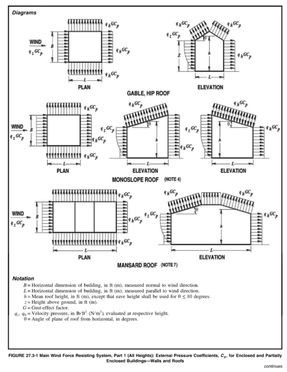
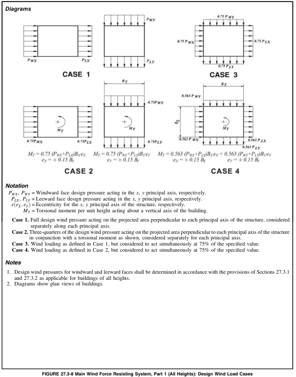
Figure 27.3-8 shows the load cases to be used for wind designs. From Figure 27.3-8, load cases 1 and 2 show wind forces to act along wind direction only (without the suction on the sides). Is it because we don't expect wind load to act in the X and Y directions simultaneously?
I don't see the wind action illustrated in figure 27.3-1 in figure 27.3-8 (basically I thought the wind will be behave as shown in 27.3-1).
Also from figure 27.3-8, we get 12 set of load cases.
[SOrry for typos. It's late here and my sleepy self reading to understand all these is making my head spin.]
When wind blows, we have the windward, leeward, and vortex (at the side of a structure). Is that what Figure 27.3-1 is trying to illustrate? From the image we can see the wind spreading perpendicularly to the wind direction.
Figure 27.3-8 shows the load cases to be used for wind designs. From Figure 27.3-8, load cases 1 and 2 show wind forces to act along wind direction only (without the suction on the sides). Is it because we don't expect wind load to act in the X and Y directions simultaneously?
I don't see the wind action illustrated in figure 27.3-1 in figure 27.3-8 (basically I thought the wind will be behave as shown in 27.3-1).
Also from figure 27.3-8, we get 12 set of load cases.
2 from case 1, 4 from case 2 (due to +/- ex and ey), 2 from case 3, and another 4 from case 4
Does the sign convection affect MT in cases 2 and 4? E.g. From Figure 27.3-8 MT is counter-clockwise when e is + and clockwise when e is -ve?[SOrry for typos. It's late here and my sleepy self reading to understand all these is making my head spin.]