Well, nowhere in seismic design is anything intended to really remain elastic. There are areas that are specifically intended to deform and behave inelastically, but the elastic nature of the remaining structure isn't an explicit intent, if I recall correctly. There are sacrificial areas, if you would, where the damage is supposed to concentrate during a design seismic event and these are done to provide adequate energy dissipation via plastic deformation.
SDC is seismic design category, it varies based primarily on the Risk Category of the building and the two/three seismic acceleration parameters, S
D1 and S
DS and perhaps the long period one I forget the nomenclature for, T
L.
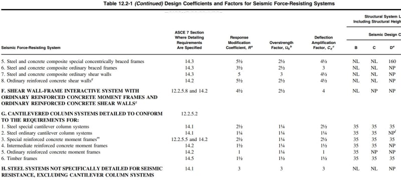
When you have a lower SDC, (A, B, C), you have to option (in steel) of not detailing for seismic resistance, so you use an R=3, the other options use more detailing and reinforcing of the various elements and allow the use of larger R values.
R value is a divisor in determining the required resistances so the higher R value produces lower forces overall, but there are areas where the steel structure must be appropriately reinforced to preserve ductility under the required seismic forces, which can increase cost, sometimes more than if you designed for larger forces and R=3 and omitted the seismic ductility reinforcements of the various sections. For higher seismic design categories the R=3 option isn't allowed. (the table below shows H. as "NP" for Seismic Design Category D, "not permitted."
This also comes up in
Steel Interchange, February 2018, Modern Steel Construction. There were a lot of articles earlier on the same subject, probably starting around 2000. And it's been discussed previously on this forum.
I've got an
FAQ on the subject (now, created due to this question).
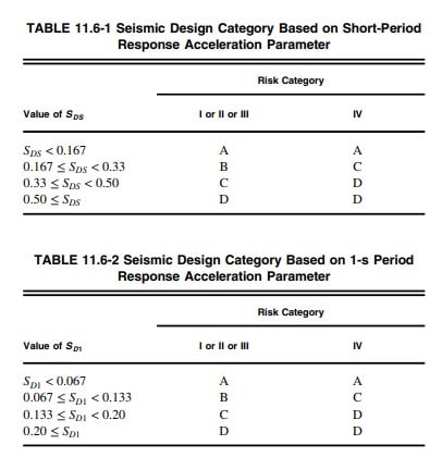
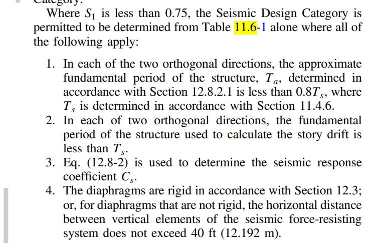
Normally design is required to be done for the more severe of the two seismic design categories determined from Table 11.6-1 (short period) and Table 11.6-2 ( 1 second period).
OP wants to wiggle into SDC C to avoid the detailing requirements, or I guess to permit R=3, which is possible in concept, provided all the correct seismic parameters cooperate.
Source: ASCE 7-16
If you can't satisfy the requirements for the exception, then you need to design for Seismic Design Category D and provide the necessary detailing and reinforcement to the steel system.
Incidentally it's unclear which version of ASCE 7 we are discussing, but the discussion here is on the use of rigid diaphragm via computation.
To your question:
Hardbutmild said:
As far as I understand the point of it all, it's primarily to check if vertical elements are connected in a way that transfers larger force to a more rigid element.
Thematically, I suppose this is correct, or close enough, or it doesn't much matter "why", but I'll delve into the semantics a bit, if you're in the mood.
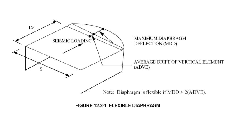
The check is to establish that the diaphragm is stiff enough to be reasonably accurate to model it as rigid, meaning that the stiffness of the diaphragm doesn't strongly influence the distribution of the lateral forces into the vertical seismic load resisting system ("moment or braced frames/shear walls") -
so when you have a relatively stiff vertical system (braced frames, shear walls), that will help produce rigid diaphragm behaviour because the deflection of the vertical elements is lower than a moment frame.
EDIT -
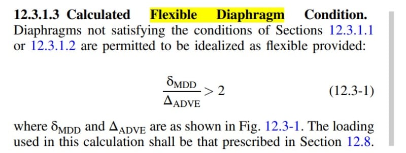
This isn't well worded. The check in question is to establish if a flexible diaphragm analysis is permitted.
It's the stiffness of the diaphragm relative to the vertical systems, so a stiffer (wall/braced frame) system means the diaphragm must be comparably stiff, a more flexible (wall/moment frame) system means the diaphragm must, again, be comparably stiff. The check is that the diaphragm deflects up to twice the average deflection of the (wall) system. If the diaphragm deflects "too much" (so to speak), relative to the vertical elements (wall), the diaphragm is permitted to be idealized as flexible. {meaning passing this check doesn't guarantee rigid diaphragm behaviour). This check doesn't prove rigid diaphragm behaviour is expected, it proves that flexible diaphragm analysis does or doesn't apply, so it's not quite the same thing, it's just something that's in the code, and if you don't satisfy it, you can't use a flexible diaphragm in the model.
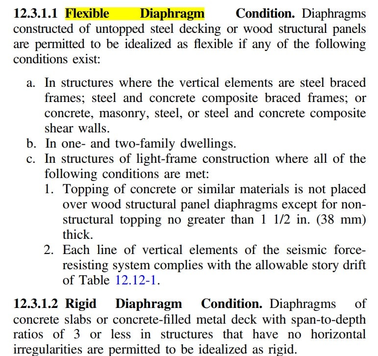
If you do "fail" this check, it indicates that a flexible diaphragm condition doesn't really exist. As a side note, for this structure, we are presuming there are steel braced frames below, more or less, or rather, typically if there's a braced frame below the untopped steel deck, it would be permitted to analyze it as a flexible diaphragm per 12.3.1.1(a)
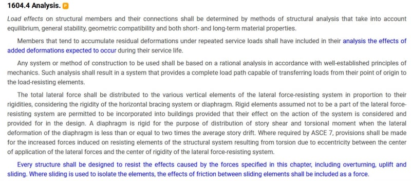
If the diaphragm is (strong enough) and stiff enough, the forces in the vertical elements will be distributed based on the relative rigidity of the vertical systems, so the one frame, if it is ten times stiffer than the other, it's going to take 10 times the lateral force, in a simplistic sense.
There are added wrinkles because you're required to add accidental torsion to increase the loads on the vertical elements, and apply the accidental torsion in both directions (up/down, left-right) and in both senses (+/-).
If you don't have a rigid diaphragm, the accidental torsion either doesn't appear or isn't required to be considered in the strength of the structure.
Louis Yaw has a paper on the analysis that's pretty digestible (
how to do rigid diaphragm analysis).
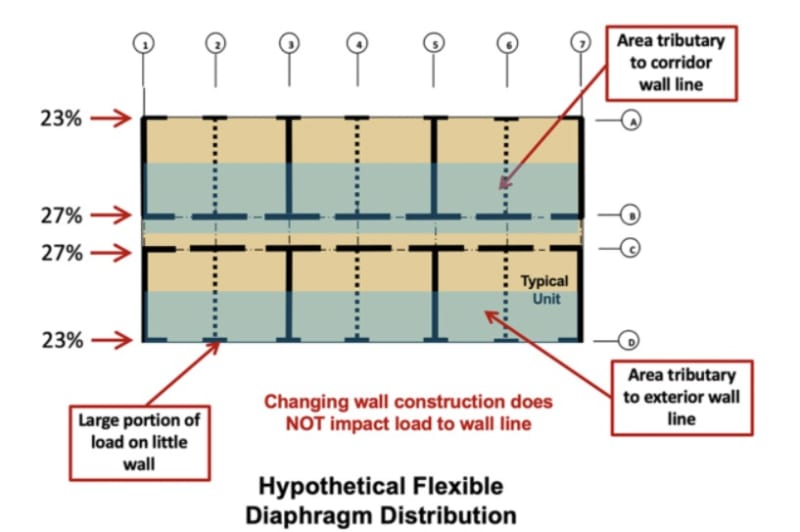
With a flexible diaphragm, the forces are distributed based on tributary length, so if there are three vertical systems, the one in the center takes more force, but not due to the stiffness of the diaphragm, it's due to the larger tributary width (half the load, say, versus 25% on the ends), provided the middle one is in the center of the building.
OP has a steel deck, conventionally this is considered a flexible diaphragm, "untopped steel decking".
Hardbutmild said:
If you have a flexible diaphragm rigidity of vertical elements has a smaller influence on force distribution which would mean that one vertical element can fail before others start yielding.
If you have a flexible diaphragm, the rigidity of the vertical elements has no effect on force distribution (this is a design simplification, so to speak, because all diaphragms have some rigidity). The sequence of failure of vertical elements isn't explicitly considered and there's no sequence of failure intended. If you design the structure appropriately, it's still expected to be damaged, during a design level event, and some of that damage will be due to design simplifications (i.e. force going where it's not intended but to an acceptable level that remains "acceptably safe").
There's
two three ways to do this -
a) provide a concrete filled metal deck diaphragm. Which will be heavy and increase the lateral forces from seismic, perhaps influence the structure below due to added weight, including foundations.
b) add another frame so the 40' distance requirement is satisfied.
c) prove it does not satisfy calculated flexible diaphragm. (Maybe) I don't think the code really says "rigid diaphragm required" if you fail this check, but it stands to reason that the force distribution based on a rigid diaphragm (or semi-rigid, maybe) would be based on rational principles of mechanics and the alternative would be less accurate.
Classifying Wood-Sheathed Diaphragms as Flexible or Rigid, Woodworks, kind of backs up my reading of c) above. And it discusses the force distributions for flexible and rigid diaphragms in a reasonably clear fashion.
In short, I think the OP is looking for a provision that doesn't actually exist in ASCE 7. It exists, just not in ASCE 7.