N
nsgoldberg
Guest
Hi All,
Used this site plenty in the past; it's a great resource, but this is my first post here. Hopefully someone can help.
I'm using WF5 and have always placed datums using the "old style" boxed callout or used the @[-A-@] technique. I'm trying to transition to the newer style (flags) and I keep hitting roadblocks. Here are the two main issues I've been having:
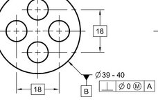
1. I can't get diametrical datums to attach to the leader lines of a dimension. i.e. datum -B- in this pic:
View attachment 6274
They will only attach to the opposite side of the dimension, on the circular feature.
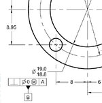
2. I'm unable to get datums to attach to a feature control frame, as in -B- in this image:
View attachment 6275
If I create the gtol, attach it to the diameter, then attempt to attach the datum to the feature control frame, I get the following error: "Gtol is in a dimension. Must place in dimension"
This is very frustrating, as I have spent several hours trying to figure it out, to no avail. I've tried changing several drawing config options, as well as my config.pro options, and nothing is taking. Here are my current (what I assume relevant) config options:
asme_dtm_on_dia_dim_gtol - on dim
gtol_datum_placement_default - on bottom
gtol_datums - std asme
gtol_display_style - std
new_iso_set_datums - yes
Thanks in advance for any help you can give.
Used this site plenty in the past; it's a great resource, but this is my first post here. Hopefully someone can help.
I'm using WF5 and have always placed datums using the "old style" boxed callout or used the @[-A-@] technique. I'm trying to transition to the newer style (flags) and I keep hitting roadblocks. Here are the two main issues I've been having:
1. I can't get diametrical datums to attach to the leader lines of a dimension. i.e. datum -B- in this pic:
View attachment 6274
They will only attach to the opposite side of the dimension, on the circular feature.
2. I'm unable to get datums to attach to a feature control frame, as in -B- in this image:
View attachment 6275
If I create the gtol, attach it to the diameter, then attempt to attach the datum to the feature control frame, I get the following error: "Gtol is in a dimension. Must place in dimension"
This is very frustrating, as I have spent several hours trying to figure it out, to no avail. I've tried changing several drawing config options, as well as my config.pro options, and nothing is taking. Here are my current (what I assume relevant) config options:
asme_dtm_on_dia_dim_gtol - on dim
gtol_datum_placement_default - on bottom
gtol_datums - std asme
gtol_display_style - std
new_iso_set_datums - yes
Thanks in advance for any help you can give.