Continue to Site

Eng-Tips is the largest engineering community on the Internet

Intelligent Work Forums for Engineering Professionals

  • Congratulations waross on being selected by the Eng-Tips community for having the most helpful posts in the forums last week. Way to Go!

Applied Moment on HSS Face - Strength Check 3

Status
Not open for further replies.

cal91

Structural
Apr 18, 2016
294
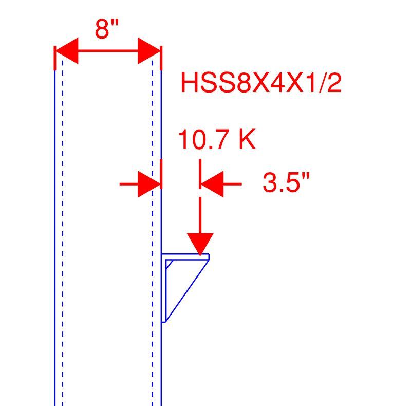
There is no other axial load in the HSS member.

There are two stiffeners that align with the HSS8x4x1/2 walls (4" apart) The welds are vertical between the angle and the HSS8x4x1/2. As such, all of the load should be directly transmitted into the web walls of the HSS, and there will be no chord plastification.

As long as the welds, angle, and stiffeners are adequate, am I wrong in stating that the strength of this connection is the full capacity of the HSS8x4 member (axial-single bending interaction)?

Capture_liervq.jpg
 
Replies continue below

Recommended for you

I agree that as long as the stiffeners align with the HSS wall and there is no opportunity for load to get transferred to the 4" wall, you can take the full flexural strength of the member. In fact, you may want to consider not welding the horizontal plate to the 4" wall to preclude such a condition
 
Check Chapter K of the AISC Specification (360-10). There are various checks in their for HSS connections - specifically the concern would involve checking your side walls against buckling due to concentrated loads from the angle/stiffener assembly.


Check out Eng-Tips Forum's Policies here:
faq731-376
 
I would follow JAE's guidance. I would resolve the moment into a force couple and then check the HSS per chapter K with a load perpendicular to the face of the HSS.
 
OP said:
am I wrong in stating that the strength of this connection is the full capacity of the HSS8x4 member (axial-single bending interaction)?

Technically, I think that would be an incorrect assumption. You're basically delivering you load straight into the side walls and creating a rather heavily taxed panel zone there. Frankly, other than FEM, I'm not sure that we really have the tools available to fully understand how those localized stresses make their way out into the rest of the cross section. The provisions that JAE mentioned are one option for dealing with some of this. But I'd be surprised if you'd have full plastic bending / axial section capacity available instantly.

All that said, your load delivery path is robust compared to other popular configurations. Short of trying to deliver axial stress to all four faces of the tube simultaneously, that's about as good as it gets. I suspect it's overkill really. You could probably have one or zero stiffeners and design the vertical leg of the angle to distribute the load out to the walls of the HSS.

I like to debate structural engineering theory -- a lot. If I challenge you on something, know that I'm doing so because I respect your opinion enough to either change it or adopt it.
 
The things I'd be concerned about are the weld between the connection and the HSS, and possible buckling of the side walls. I doubt the latter is going to be a huge concern on most HSS sections, though. I'd probably also make an assumed shear panel where I put an assumed force couple into the HSS and checked the panel zone for shear.

I'd be assuming that the only welds doing anything for bending are the vertical welds that go into the HSS walls.

It's probably pretty strong, but not necessarily full strength.
 
If the stiffeners align with the HSS walls, there may be a problem with the vertical weld as it occurs at the curved corner of the HSS. If the angle is not welded to the 4" wall, there is a tendency for the weld at the 8" wall to unzip from top down.

cal91 said:
As long as the welds, angle, and stiffeners are adequate, am I wrong in stating that the strength of this connection is the full capacity of the HSS8x4 member (axial-single bending interaction)?

It is not only wrong to state that, it is not relevant. The connection must be capable of supporting a 10.7k load at an eccentricity of 3.5" from the face of the HSS whereas the HSS must be capable of supporting a 10.7k load at a 7.5" eccentricity with unspecified boundary conditions.

BA
 
JAE said:
Check Chapter K of the AISC Specification (360-10). There are various checks in their for HSS connections - specifically the concern would involve checking your side walls against buckling due to concentrated loads from the angle/stiffener assembly.

I have checked Chapter K, and the only provisions for applied moments on the face of an HSS assume it's a plate in the middle of the chord, which results in chord classification for a failure mode. This would be overly conservative for my design.

KootK said:
Technically, I think that would be an incorrect assumption. You're basically delivering you load straight into the side walls and creating a rather heavily taxed panel zone there. Frankly, other than FEM, I'm not sure that we really have the tools available to fully understand how those localized stresses make their way out into the rest of the cross section. The provisions that JAE mentioned are one option for dealing with some of this. But I'd be surprised if you'd have full plastic bending / axial section capacity available instantly.

All that said, your load delivery path is robust compared to other popular configurations. Short of trying to deliver axial stress to all four faces of the tube simultaneously, that's about as good as it gets. I suspect it's overkill really. You could probably have one or zero stiffeners and design the vertical leg of the angle to distribute the load out to the walls of the HSS.

TLHS said:
The things I'd be concerned about are the weld between the connection and the HSS, and possible buckling of the side walls. I doubt the latter is going to be a huge concern on most HSS sections, though. I'd probably also make an assumed shear panel where I put an assumed force couple into the HSS and checked the panel zone for shear.

I'd be assuming that the only welds doing anything for bending are the vertical welds that go into the HSS walls.

It's probably pretty strong, but not necessarily full strength.


These are the answers I was looking for, thanks. I knew chord plastification failure (Section K) would be over conservative, but didn't feel right in taking the entire section properties knowing that the 8" faces would have a huge shear demand. So would a good estimate for the capacity of this connection be the load required to cause shear stress failure in the wall?

BAretired said:
If the stiffeners align with the HSS walls, there may be a problem with the vertical weld as it occurs at the curved corner of the HSS. If the angle is not welded to the 4" wall, there is a tendency for the weld at the 8" wall to unzip from top down.

I understand but wouldn't that happen only when the stress in the weld at the top exceeds the strength of the weld? Or is there an earlier failure having to do with the curved corner?

BAretired said:
It is not only wrong to state that, it is not relevant. The connection must be capable of supporting a 10.7k load at an eccentricity of 3.5" from the face of the HSS whereas the HSS must be capable of supporting a 10.7k load at a 7.5" eccentricity with unspecified boundary conditions.

True, and it can. But that is not what my question was. I was wondering what the capacity of the connection is.

 
cal91 said:
So would a good estimate for the capacity of this connection be the load required to cause shear stress failure in the wall?

For example, say the load applied is "X" kips.
Shear stress is X/2 / (6" * 0.465") = 0.18 X ksi
transverse stress is -(X*3.5" / 2 ) / (0.465" * 6" ^2 / 6 ) = -0.63 X ksi,
Longitudinal stress is the stress in the chords, or X/2 / (6"*0.465") = 0.18 ksi

Using Mohr's Circle I can find the maximum Shear Stress = Sqr Root { [(σ₁-σ₂) / 2 ]² + τ² } = 0.45 X ksi

For Shear Failure,

0.45*X ksi = 0.9 * (0.6 *Fy=46ksi)
X = 55 kips

Compare to X*7.5" = 0.9*(Fy=46 ksi) * (Zx = 17.9 in³) = 99 kips
Compare to X*7.5" = 0.9*(Fy=46 ksi) * (Zx = 23.5 in³) = 130 kips

So determining the strength of the connection based upon first shear yielding, the connection has a capacity 56% of it's elastic capacity, or 42% of it's plastic capacity.
 
If your intent is to avoid loading the face of the HSS, you might consider lapping vertical plates to each side of the column that extend out past the face to support a bearing plate. Like a steel corbel. You could use C-shaped fillet welds from the vertical plates to the side walls. Design checks are more straightforward and you avoid the flare bevel groove welds which are harder to make properly.
 
Cal91 said:
I understand but wouldn't that happen only when the stress in the weld at the top exceeds the strength of the weld? Or is there an earlier failure having to do with the curved corner?

I would say yes, that only happens if you overstress the weld. Be careful at your weld strength assumptions, though. An unreinforced flare bevel weld wouldn't develop the full HSS wall strength (i.e. it isn't full penetration).
 
Status
Not open for further replies.

Part and Inventory Search

Sponsor