Continue to Site

Eng-Tips is the largest engineering community on the Internet

Intelligent Work Forums for Engineering Professionals

  • Congratulations Danlap on being selected by the Eng-Tips community for having the most helpful posts in the forums last week. Way to Go!

Anchor grp pipe support one meter from grp tank ?. Please help me with better support design 4

Status
Not open for further replies.

drakkkko

Mechanical
Feb 9, 2011
64
Hi,

I was asked to review the loads on some supports of a GRP (Glass Reinforced Plastic) pipe, which is gravitational, performing a flexibility analysis. The support arrangement is copied from other projects, whose pipe is geometrically similar with the same service.
This pipe feeds a tank of GRP material and according to the engineering drawing there is an anchor type support positioned one meter from the tank nozzle, with elevation of half a meter from floor level.

I have no experience in the design of line support that feeds a GRP tank, but personally I would not place an anchor so close to the nozzle of a tank (much less if this tank it is made of GRP material). According to those who have been working for years in this company, there are already other projects that have done this.

Finally I would like to recommend another type of support, but as I explained, I have no experience in designing support for a grp tank.

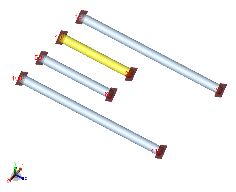
Please help me if you have experience in this type of design. I add a drawing (Fig. N°1) showing the pipe entering the tank with dimensions in milimeters.

The information to consider is as follows:

The pipe is gravity, diam. = 24 [inch] with an equivalent static head of 30 kPa.
S.G: fluid : 1.23
Temperatures:
-T° fluid : 61 °F
-T° min ambient= 14 ° F
-T° max ambient= 89.6 ° F
-T° installation= 50° F

Thanks in advance.
 
 https://files.engineering.com/getfile.aspx?folder=02acf31d-a5de-456e-a8ce-f7e499594860&file=Fig._N°1.jpg
Replies continue below

Recommended for you

I have used similar design in many installations for support of carbon steel piping at pumps and have seen it done also by others. There is a need to stop the thermal growth of piping into and resulting forces and moments at pump nozzles. Putting an anchor as close to the pump nozzle as possible will absorbe the thermal deflection/forces, and with such short distance between the anchor and the pump nozzle there is very little thermal growth in the pipe in that short secton to really cause any issues on the pump nozzle. Although if you run a computer calculation stress analysis with an anchor a couple of feet off the pump nozzle and with the pump nozzle itself simulated as an anchor you will get very very high loads developed (because the program only looks at theoretical forces) these theoretical loads are not real if the actual thermal growth is only 0.005 inches or so because there will be some give/flexibility in the nozzle connection. I would then just model the pump nozzle as a free end and run the stress analysis only up to the anchor on the piping. If the piping temperature is too high you would have to be careful though since there could be significant thermal growth in only 2 feet of piping between anchor and pump nozzle.
 
The anchor would typically be a dummy leg welded to the process pipe that is adjustable in height with a bolted baseplate.


- Typical anchor support would be single leg steel support with clamp.

- Typical guide support would have craddle and U bolts on single leg T support

I will suggest you to look AWWA M45 Fiberglass Pipe Design


- Apparently the GRP tank is aboveground vertical cylindrical tank . The foundation could be pad foundation having octogonal , circular shape with thick around 500 mm ..


I cannot give you the formula for success, but I can give you the formula for failure..It is: Try to please everybody.

 
FRP (GRP) pipe has to be treated special, not like you would consider metallic piping. For process piping, ASME NM.2 is the standard you would be looking for. There are a few factors that make FRP piping unique (some listed below):
1) Low elastic modulus allows anchor supports in line with other anchors.
2) Compressive modulus differs from tensile modulus due to glass orientation.
3) The material is anisotropic, so properties are not the same in all directions.
4) Pressure expansion of the pipe is non-negligible due to the lower elastic modulus.
5) Lower temperature deltas are relevant due to the piping being a thermoset compared to metal.
6) Material properties are unique to manufacturers, so identifying the manufacturer of the FRP pipe is a critical first step.

It is entirely possible that an anchor support so relatively close to the nozzle is acceptable, but it should be analyzed. If you have no experience with FRP and no one you can rely on internally, it would be better to bring in an engineer who does have experience with that. FRP pipe stress is easy to get wrong if you do not know what you are doing.
 
Snickster,

Not sure I agree with your contention that the pump/equipment nozzle loads are "theoretical" with a pipe anchor nearby. Yes, 2 feet of piping will grow a very small amount. But a good pipe stress model should also have the movement of the nozzle itself factored in, not just a floating nozzle like you imply.

The equipment/pump nozzle will move based on that equipment anchoring and nozzle dimensions. The pipe anchor is likely not a perfectly rigid anchor and that stiffness could be reduced to be more realistic. But I disagree with calling these "theoretical" loads and have seen damage & high forces from pipe anchors near equipment by people thinking they were solving the problem.
 
Thermal stress is not dependent on length; only on temperature and degree of fixity.
Thermal axial force is not dependent on length; only on temperature and cross sectional area.
Don't get fooled by nozzles in close or far proximity to any anchor.
Only total displacement is dependent on length. A short length may only cave the tank in a small amount; a long length may result in a bigger cave in, but stresses were initially equal before relieved by the resulting displacement.

--Einstein gave the same test to students every year. When asked why he would do something like that, "Because the answers had changed."
 
That's only true for perfect/ideal anchors, which Peng talks about in their book.

Even a quick model like the one attached shows this isn't true for real/imperfect anchors.
Anchor_Test_pi2cgf.png

Element 10-20 is 5 ft long while Element 15-25 is 10 ft long. Both have perfect anchors and see the same loads as expected. Element 50-60 is 5 ft long and Element 100-110 is 10 ft long, but the "TO" node has imperfect anchors and their loads vary.
 
Too many designers use steel terminology and design.

A GRP anchor is actually very hard to do without severely damaging the GRP pipe.

I would use some sort of flexible or bellows arrangement at the tank connection and just let this pipe move more or less where it wants to within a guided system. As soon as you introduce point loads clamps or things like that, GRP just destroys itself as it does if you try to have any sort of bending moment like an expansion loop.

GRP can be good, but is not steel and you need to think completely differently.

And don't get me started on how you joint this stuff.... your flange connection and that 20degree bend have bene drawn as if it was steel with a butt weld.

It isn't anything like that and getting any bend like 20 degrees is possibly a special order from the vendor. Tell whoever designed this rubbish to go get a suppliers manual and study it.

Remember - More details = better answers
Also: If you get a response it's polite to respond to it.
 
RVAmeche
Your right. The loads are really there but just a little deflection will quickly eliminate them if you are talking about hundredths of inches. Now I would be careful if the deflection is about 1/16 inches or more at a pump nozzle because it could cause unwanted vibrations. There really is not many options available for limiting the loads on a pump nozzle, except maybe using expansion joints, but most clients want to avoid that if possible. For a tank or vessel with a with deflection on the order of hundredths of an inch, it will just cause a little elastic deformation of the shell or at worst a little plastic deformation of the shell but not failure if the loads are not cyclical, but API 650 or ASME B&PV Code calculation methods should be strictly followed, and good engineering judgement/practice.
 
Seems like a case for the GRP manufacturer and/or a specialist GRP design house to solve (that’s how I’ve seen it played out in oil & gas companies where it is made part of the piping material purchase order).

Steve Jones
Corrosion Management Consultant


All answers are personal opinions only and are in no way connected with any employer.
 
RVAmeche
" ... and degree of fixity. "

--Einstein gave the same test to students every year. When asked why he would do something like that, "Because the answers had changed."
 
GRP tanks are structurally extremely weak even if the nozzles have repads. They will not take any nozzle reaction forces or moments at all.

Never put an anchor (definition of anchor = 6 DOF fixed) as the first support off the tank nozzle. It *will* overload the tank nozzle.

Imperative that you take into account flexibility of all supports in the system. They are not rigid and assuming they are is a huge error in FRP/GRP piping and equipment (metallic pipe too, actually).

You can't model the tank nozzle in NozzlePro because NozzlePro does not do composite materials. No help there. So... if this is critical or hazardous fluid service, you can hire an FRP consultant (there is a really good one in Florida) that will develop the allowable forces and moments that can be applied to the nozzle. You then use those loads in your favorite pipe stress program to make sure your nozzle is not overloaded. That procedure will give you a defensible answer based on fundamental mechanics that passes the reasonable man standard. Is that analysis accurate? Probably within 25%. Everybody hangs their hat on CAESAR II et al. but I can guarantee you the results are not as accurate as you think they are especially when non-isotropic composite materials are involved.

If there is any temperature involved at all, you will likely need an expansion joint (or two). Even solar heating can be a problem if the tank is outdoors. If the line is out of service and sits in the sun in hot weather it can get up to 120° or better. You have to account for that. FRP/GRP has much higher alpha than metallic materials.

Don't forget to allow for settling of the tank foundation. That right there applies a vertical displacement to the piping. All tanks settle.

Good luck, BTDT got the bruises, bloody knuckles and bloody t-shirt.

 
Great Post.

I'd missed the fact that the tank was GRP as well which makes the anchor an even worse idea that before.

The key with GRP for me is to make everything as flexible as possible. Sticking an anchor in the system is just adding a rock in which to break the system. IMHO.

Remember - More details = better answers
Also: If you get a response it's polite to respond to it.
 
Status
Not open for further replies.

Part and Inventory Search

Sponsor