Hi,
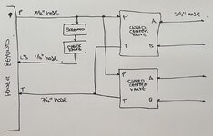
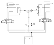
I am working on connecting a pair of closed-center proportional control valves in parallel to my tractor. The valves have P, T, A and B connections. The tractor has a closed center pressure-flow compensated system that has a load sense port. The pump has a max output of 25 GPM at 2,500 PSI.
My understanding is that if I leave the valves closed then the pump will continually run at high pressure standby and this could generate excessive heat and damage the pump, as well as consuming more diesel. I am looking at how to take advantage of the load sensing capability on the tractor.
My current plan is to add a tee into the P line between the tractor and the valves. From this tee I will connect a normally-closed solenoid which integrates a check valve. The output of the solenoid will go back to the load sense port. In the tractor there is a 0.020" bleed down orifice for the LS.
The P line will be 3/4" hose and the load sense will be 1/4" hose.
My software will automatically open the LS solenoid one second before any valve control and then automatically close the LS solenoid five seconds after the last valve control, so the operator does not have to do anything manually to make this work.
Is that the correct approach or is there a better way without modifying the valves (which is not going to be possible)?
Thanks! Andy

Last edited:

