Continue to Site

Eng-Tips is the largest engineering community on the Internet

Intelligent Work Forums for Engineering Professionals

  • Congratulations waross on being selected by the Eng-Tips community for having the most helpful posts in the forums last week. Way to Go!

ACI Shear Hangers in Girders/Joists

Status
Not open for further replies.

StrEng007

Structural
Aug 22, 2014
543
Although not addressed in ACI 318-14, ACI document 314-14 Guide to Simplified Design for Reinforced Concrete Buildings, Section 8.5.5.1, addresses the need for hanger ties used to reinforce a joist to girder beam connection (see equation 8.5.5.1). Is this equation derived from the beam chapter or reinforcing chapter of 318-14? The topic is discussed in ACI 318-19 Section R9.7.6.2.1. However, 318-19 does not provide any equations.

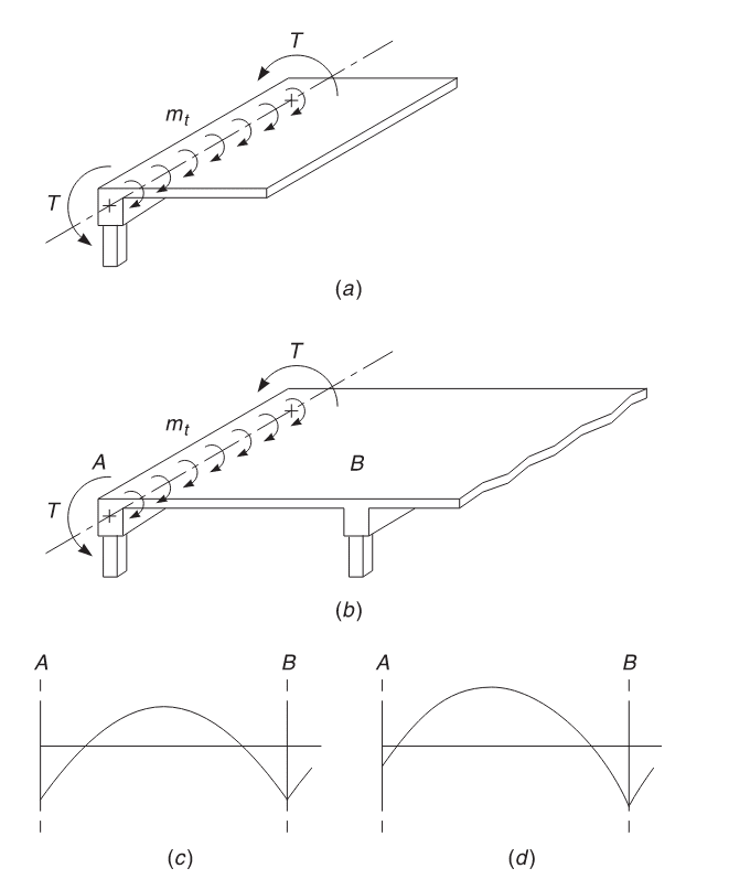
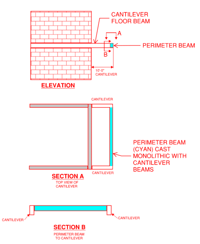
I have a perimeter beam that is cast monolithically with concrete girders that cantilever off the vertical system of the building. I would like to consider the perimeter beam as simply supported between the cantilevers, especially at the end bay. I don't want additional torsion on the end of the cantilever. I understand there will be torsion due to shear. The goal is to prevent torsion due to moment transfer.

Are there any special detailing requirements that would allow me to make this simple span assumption?

There will be shear reinforcing vertical ties at the end of the supported beam, and (2) longitudinal top bars will be provided for ease of construction. These (2) top bars will develop some fixity at the girder. How do I eliminate moment fixity at this location? Does the shear reinforcing equation from 314-14 account for this? Or would additional torsion ties need to be added to the amount of shear reinforcing from equation 8.5.5.1 in ACI 314-14?
 
Replies continue below

Recommended for you

StrEng007 said:
Is this equation derived from the beam chapter or reinforcing chapter of 318-14? The topic is discussed in ACI 318-19 Section R9.7.6.2.1. However, 318-19 does not provide any equations.

The equations for this originate from strut and tie theory I believe. While I think that the hanger reinforcing is a great idea (mandatory in Canada), a lot of buildings in the US have gotten by without it for a very long time.

StrEng007 said:
Are there any special detailing requirements that would allow me to make this simple span assumption?

You'll likely want to look into compatibility torsion requirements which allow you to cap the amount of torsion in the supporting beam to that which would allow it to crack and redistribute it's torsion as flexure in the supported member. That said, one place where this tends to work a bit poorly is for supported beams that tie in close to columns. And that kind of sounds like your situation. How close will your perimeter beams be to your columns? What are the proportions of your girders and joists?

StrEng007 said:
How do I eliminate moment fixity at this location?

Practically speaking, you don't. The best that you can hope for is the compatibility torsion setup that I mentioned above. You might achieve something similar to what you are wishing for by minimizing your top bars at the support and, thereby, limiting the torsion coming into the girder to that amount of torque. Problems with that strategy:

1) Theoretically speaking, you would now need to deal with the over strength moment capacity of the supported beam as the torque in the girder. So a phi factor of 1.25 rather than 0.9.

2) Too little top steel in the joists may create crack control problems that can lead to shear capacity problems. Historical practice has been to provide top steel that provides negative moment capacity 0.25-0.33 times your positive moment capacity as a minimum even if you design your beam as simply supported. This is what I do.


KootK said:
allow it to crack and redistribute it's torsion as flexure in the supported member
Please see the example image below (taken from Design of Concrete Structures 15th Edition, Darwin, Dolan, Nilson). Note, this is not my particular scenario but I need to first establish the general theory before we look at my specific case.

The perimeter (spandrel) beam at the slab edge attracts torsion due to the slab edge's unresolved negative moment (moment diagram shown in Section C). If we allow cracking to occur the moment redistributes itself, in this case larger positive mid span moment within the slab.

Question #1: Is the relief in moment due to cracking of the spandrel at it's ends, rendering the entire beam to be torsionally flexible? Or is it a local crack at the interface between the slab edge and the spandrel?

Screenshot_1_gpilpk.png


For this situation, compatibility torsion looks acceptable because the slab has more than one way to permeate flexure through the system.

Is my understanding correct that Tu is the resultant torsion that acts over the entire span of the spandrel beam? IE, we don't need to calculate any local (1 ft strip) version of Tu to first check the local interaction between the slab and the spandrel beam?

Now, if Tu ≥ ΦTcr, and Tu can be reduced via moment redistribution, the Code permits us to reduce the Tu value down to ΦTcr in accordance with ACI 318-14, Section 22.7.5.

Question #2: If I compare the original Tu, calculated from the original analysis, and Tu < ΦTth, then I may neglect all torsional effects?
Question #3: If the original Tu > ΦTth, but I allow a reduction of Tu to ΦTcr, then I need to design shear reinforcing for ΦTcr which is essentially 4x the threshold torsion for solid non-prestressed cross sections?
Question #4: What is the simplest way to determine the higher demand on the slab's positive moment due to reduction of stiffness at the perimeter beam?

Please see the image below for my actual condition:
KootK said:
How close will your perimeter beams be to your columns? What are the proportions of your girders and joists
Screenshot_2_zo74er.png


I basically have a perimeter beam that cantilevers out and has a perimeter beam cast monolithic with each end.
I'd like the loading from the cyan portion to provide (1) shear reaction at each end of the cantilevers. I don't want to impart negative moment to the ends of the cantilever.

Based on the above sections, my plan is to:
1. Determine the simple span moment and shear from the cyan part of the beam.
2. Apply shear reactions from #1 in addition to the ledger load acting along the cantilever. I would then calculate Vu and Tu at the interface between the cantilever and the supporting wall (the total loading for the full 10 ft cantilever).
Please confirm the Tu will be checked at the support of the cantilever beam and not the interface between the cyan and cantilever.
3. If Tu < ΦTth, then I may neglect all torsional effects.
4. If Tu > ΦTth, then I must consider torsional reinforcing and I can set Tu to ΦTcr.
5. From the combination of Tu and Vu, I can determine the torsion reinforcing in the beam.
6. In addition, at the interface between the cyan and the cantilever, I'd will provide hanger reinforcing per ACI 314-14.
 
KootK,
Looking at this again, I believe I'd need to maintain Equilibrium Torsion for this cantilever girder. Allowing it to crack in order to re-distribute moment seems like it could create a failure mechanism.

Typical textbook examples consider a spandrel beam that has 2 points of support. I'm reluctant to try to allow the cantilever end to behave this way.

The other issue I'm up against is how to rationalize the end moments of the joist. It will impart a moment somewhere between 0 and wL²/12 at the cantilever girder.

KootK said:
Historical practice has been to provide top steel that provides negative moment capacity 0.25-0.33 times your positive moment capacity as a minimum even if you design your beam as simply supported.
So you're saying to provide enough negative steel (top bars) to develop a fixed end moment equal to wL²/32 to wL²/24, and allow the mid-span to take the full wL²/8? Will this allow the joist to "crack" and redistribute back to the mid-span? My understanding is the compatibility equations want us to allow the spandrel to crack at it's supports, not the joist end connection to the spandrel...?

Do you know of any texts that illustrate how to design the beam in-between a fixed end and pinned end condition? Typically I determine moment assuming fixed ends then size the reinforcing. Here, it seems like you're suggesting I determine a percentage of steel negative steel (as a % of the positive reinforcing), then determine the moment capacity and ignore the traditional beam diagrams. How can I be sure the connection won't try to develop that wL²/12 end moment, fail in flexure, crack, and then create a shear issue as you mentioned?
 
There's more here than I can deal with quickly so I'm going to try to deal with the big stuff first and see where that gets us.

OP said:
Looking at this again, I believe I'd need to maintain Equilibrium Torsion for this cantilever girder. Allowing it to crack in order to re-distribute moment seems like it could create a failure mechanism.

I disagree, this approach is ubiquitous in RC concrete. I would also say that your cantilever span is long enough for this to be sensible.

OP said:
Please confirm the Tu will be checked at the support of the cantilever beam and not the interface between the cyan and cantilever.

That's right. Tu is your peak torsion which usually occurs at the supports.

OP said:
The other issue I'm up against is how to rationalize the end moments of the joist. It will impart a moment somewhere between 0 and wL²/12 at the cantilever girder.

Design it as simple span while providing "detailing" top steel at the ends providing a negative flexural capacity 1/2 - 1/3 of the midspan positive flexural capacity.

OP said:
Do you know of any texts that illustrate how to design the beam in-between a fixed end and pinned end condition?

Not off of the top of my head. CRSI may be the source of the 1/3 - 1/2 recommendation.

OP said:
How can I be sure the connection won't try to develop that wL²/12 end moment, fail in flexure, crack, and then create a shear issue as you mentioned?

You can't be sure. You have to:

1) Allow it to crack if the moment is exceeded.

2) Provide some top steel to gain some measure of crack control.

3) Most importantly, provide some top steel to ensure that your effective shear depth is something close to the height of the beam.

OP said:
I don't want to impart negative moment to the ends of the cantilever.

Recognize that this is not fully achievable. The redistribution procedure allows you to cap the amount of torsion in the girders to a significantly lower level than your elastic analysis predicts. There still is some torsion in the system however and the torsion developed in the girders will need to be rectified at their supports. I'm not see columns supporting your girders here which makes me wonder about this part.

If you really want no torsion / negative flexure, the answer to that is a joist that is very stiff flexurally compared to the torsional stiffness of the girders. And even then, "no torsion" will still be a condition that you approach asymptotically but never actually achieve.
 
Status
Not open for further replies.

Part and Inventory Search

Sponsor