Continue to Site

Eng-Tips is the largest engineering community on the Internet

Intelligent Work Forums for Engineering Professionals

  • Congratulations KootK on being selected by the Eng-Tips community for having the most helpful posts in the forums last week. Way to Go!

ACI 350 Environmental Concrete Flexure Design 1

Status
Not open for further replies.

CStruc

Structural
Oct 4, 2017
5
I am working on my first concrete tank design and using ACI 350-06 for the first time. I am working on the wall flexure design checks, and I thought I understood how to correctly determine/apply the Sd factor. However, I am a bit confused after looking back at this old thread from 2010:

thread507-273684

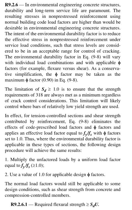
JAE indicated that a Phi of 1 (φ = 1.0) is to be used when checking against the increased moment values with Sd. Again, I am new to 350, but this is not how I understand the procedures given in chapter 9 requirements. I do see that an equivalent procedure is given in the commentary (R9.2.6, paragraph 3), which, from my understanding, can be summarized as this: Sd x U = fy/fs x (unfactored loads). But if you are going to calculate Sd using eq. 9-8, then the approach: φMn ≥ Sd*LF*(M_service) would become UNconservative if a φ=1 is used when 0.9 is needed.

Would JAE (or anyone) please give me some input or their thoughts on this.

Much appreciated!
 
Replies continue below

Recommended for you

CStruc - the φ = 1 concept came direct from the ACI 350-06 commentary - see below:

Sd_commentary_lyplws.jpg


Check out Eng-Tips Forum's Policies here:
faq731-376
 
Thanks JAE. I thought that was the part you may have been referring to. In that commentary, prior to providing the two-step procedure, it states that: "where the environmental durability factor is applicable in these types of sections, the following design procedure will achieve the same results". So I take this statement as this being an ALTERNATIVE approach. But if you look at the whole factored load procedure, you get:

Sd = (φ*fy)/(γ*fs), so ==> φMn ≥ [(φ*fy)/(γ*fs)]*LF*(M_service)

So if: (γ = LF), this would cancel-out. In addition, you could cancel phi (φ), on either side of the equation, as long as they have been applied consistently on BOTH sides of the equation. You had provided a spreadsheet example (attached) in the previous thread, and you used φ = 0.9 in your determination of Sd. So if you do use 0.9 in your determination of Sd, you would need to use it on the other side of the equation or safety would be reduced. This is where I became confused.


Since commentary R9.2.6 even states that Sd in Eq. 9-8 "eliminates the effects of code-prescribed load factors and φ factors and applies an effective load factor equal to fy/fs with φ factors set to 1.0" why even waste time with the typical load factors at all? I am now unsure if this is even considered strength/factored design or serviceability design?
 
I am looking at this right now as well.

If you have just earth pressure on an empty buried chamber, the load factor ratio (gamma) is 1.6. If your flexural section is tension controlled and you allow a stress or 24,000 psi, then Sd is .90*60/(1.6*24)= 1.40625.

Sd*U is 1.406258*1.6*H or 2.25H.

This is equal to (Fy/Fs)*0.90*H = 2.25H

Which is close, but slightly more conservative, than the 1.3 "sanitary factor" people used to apply across the board when the load factor was 1.7. I.e. 1.3*1.7*H = 2.21*H.


Thanks for the input JLNJ.

I think I am seeing the 9.2.6 requirements as more of an allowable stress/service-level check now after seeing how the commentary explains that the Sd pretty much eliminates the effects of code prescribed load and resistance/phi factors.


For example, in JLNJ's above post, the: (Fy/Fs)*0.9*H is the required strength, but if you eliminate the phi=0.9 from this as well as from being multiplied by the nominal strength on the other side of the equation, you would have (Fy/Fs)*H = (60/24)*H = 2.5*H. If you would simply divide both sides of the equation by the 2.5, you would get: 0.4*(nominal strength)≥ (service load). Basically a 0.4 allowable.
 
Sorry if I went off on a tangent. Maybe the Sd will make more sense to me as I get more design experience applying it. At first glance, it just seems that in the same section that Sd is defined (9.2.6), the commentary provides a work-around.

Thank you bones206. I will take a look.

 
I get my design moments and forces from FEM analysis. Since those are enveloping several load combinations, I have found the alternative approach from the commentary to be more straightforward to implment.
 
bones206

I have been sidetracked from this project a good bit in the past couple of weeks. I am just getting back into the thick of things, and have taken a look at your example calc. I see that you check for the moment/bending in your example, but I was wondering if you take tension into consideration if this is for tank walls (i.e. combined axial tension & bending)?
 
Yes I reduce the reinforcement available for flexure by the amount required for axial tension. I may have cropped out that page in the attachment.
 
Status
Not open for further replies.

Part and Inventory Search

Sponsor