Continue to Site

Eng-Tips is the largest engineering community on the Internet

Intelligent Work Forums for Engineering Professionals

  • Congratulations IRstuff on being selected by the Eng-Tips community for having the most helpful posts in the forums last week. Way to Go!

ACI-318 Anchorage (Ninjas apply here)

UTvoler

Structural
Oct 7, 2010
55
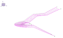
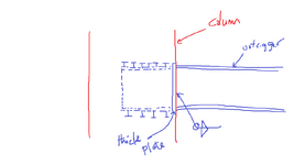
Hello all you ACI anchorage experts! I am soliciting for opinions on a fun one: I have a round CIP concrete building column supporting three W27 cantilever outrigger beams (supporting a massive ornamental stair). The outriggers will be connected to the column via an embed plate (see attached). How do we tackle the anchorage evaluation on this one (I am the delegated designer, and get to provide the calc package that shows this embed and connection is good) per ACI 318-14 (Ch. 17 presumably). I have run a simplified preliminary analysis using Profis, and it doesn't seem too far out the realm of possibility of working.

Thoughts on the approach for analysis??? I'm trying to wrap my head around the three tensile forces due to bending projecting outward in different directions from the round face; maybe some WAG combined vector of the tensile force against the capacity of the breakout of most of the column? Thanks in advance!
 

Attachments

  • Stair Outrigger.pdf
    386.5 KB · Views: 46
Replies continue below

Recommended for you

The circular column allows a final resultant to be applied as though it were aligned with a major axis...whichever direction that resultant occurs. Not a big deal there.

But I feel like I'd want to allocate certain anchors to certain outriggers alone and not count on multiple sharing of load...not sure I can explain why but it feels safer.

Also - since this is a very non-redundant design - I'd be inclined to add safety factor to it all...even an additional factor of 2.0 maybe.
(as an aside, when working on a large domed stadium using stay cables the design was certainly non-redundant - a line of cables fails and the whole roof comes down - so we added an additional line of strands to add to the overall safety factor as an effort at responding to the lack of redundancy).
 
One other thought - unfolding the anchors is probably necessary to use Profis but when you do that the "outer" anchors assigned to a particular outrigger will naturally shed some real-life shear (due to their orientation with respect to the outrigger) and take on more direct tension from the math. Not sure how you account for this.
 
Better you than me.

What is the thought process in only providing a semicircle for an embed plate? Would it be possible to case a full circular plate?

As JAE said, you are going to have to do some mental gymnastics to get this into a 2D analysis.
 
Any chance you can convince them to do a steel column and then encase the whole thing in concrete? Controlling cracking might be tricky, but I'd feel a lot better about the whole thing...

EDIT: or, cut the ends of the beams to match the curvature of the column. Then laser cut the projected profile of the beam into opposite "faces" of a large round tube column the size they want the final column to be. Slide the beam in and weld it to both penetrations. then fill that with concrete. grind down the welds for some AESS and paint the whole thing.
 
The circular column allows a final resultant to be applied as though it were aligned with a major axis...whichever direction that resultant occurs. Not a big deal there.

But I feel like I'd want to allocate certain anchors to certain outriggers alone and not count on multiple sharing of load...not sure I can explain why but it feels safer.

Also - since this is a very non-redundant design - I'd be inclined to add safety factor to it all...even an additional factor of 2.0 maybe.
(as an aside, when working on a large domed stadium using stay cables the design was certainly non-redundant - a line of cables fails and the whole roof comes down - so we added an additional line of strands to add to the overall safety factor as an effort at responding to the lack of redundancy).
Yes; I'm looking for some redundancy for sure!
 
Better you than me.

What is the thought process in only providing a semicircle for an embed plate? Would it be possible to case a full circular plate?

As JAE said, you are going to have to do some mental gymnastics to get this into a 2D analysis.
That's why they pay me the big bucks! Lol....The two-piece is what the SER detailed on the contract drawings, so that's what the fabricator started with. But we are moving to a 3-piece fully circular plate.
 
Thanks for the input, I've talked it over with the fabricator and we're going to go with a 3-piece full circle "embed". The joints will be field welded, partial pen (or whatever I spec). Do I get to completely ignore any tensile loading in the anchors now, and just use them to feel comfortable in resisting the vertical shear?

As always, thanks for the input this forum is awesome!
 
Do I get to completely ignore any tensile loading in the anchors now, and just use them to feel comfortable in resisting the vertical shear?

I feel not. Given the proportions, I suspect that the only way to mobilize the hoop stress will be to first fail the anchor frustums as those will be the stiffest load path initially.
 
I would actually like to see you get rid of the outrigger highlighted in yellow altogether unless I miss my mark with respect to how the stair will be framed.

If the stingers are continuous and deep as I suspect, that middle outrigger may wind up in uplift which would create a prying effect that would:

a) increase the downward load on the other two outriggers and;

b) make the load distribution very difficult to predict.

As an added benefit, it would then become very simple to analyze the two outrigger connections that would remain given that I would would not expect them to interact meaningfully.

All of that said, I realize that getting EOR's to change something they've put on paper is all but impossible in many cases.

c01.JPG
 
For something where the stakes are high like this, I would favor an old school, "pre-Profis" connection with some built in ductility. You sell it on the merits of the tolerance argument and, perhaps, by appealing to the architect on the basis of "what tends to resonate with a lay person as structurally appropriate".

c01.JPG
 
I would actually like to see you get rid of the outrigger highlighted in yellow altogether unless I miss my mark with respect to how the stair will be framed.

If the stingers are continuous and deep as I suspect, that middle outrigger may wind up in uplift which would create a prying effect that would:

a) increase the downward load on the other two outriggers and;

b) make the load distribution very difficult to predict.

As an added benefit, it would then become very simple to analyze the two outrigger connections that would remain given that I would would not expect them to interact meaningfully.

All of that said, I realize that getting EOR's to change something they've put on paper is all but impossible in many cases.

View attachment 10430
Koot, the EOR detailed without the middle outrigger as you are suggesting. The stringers are relatively shallow (17" channel shown on the arch dwgs); we pretty well settled on HSS 20x8x5/8 as the delegated designer. The delegated design came with some pretty stringent deflection/vibration criteria and I added the middle outrigger to reduce the deflection. I still get all downward deflection with the third outrigger though.
 

Attachments

  • Deflection.png
    Deflection.png
    42.5 KB · Views: 17
The stringers are relatively shallow (17" channel shown on the arch dwgs); we pretty well settled on HSS 20x8x5/8 as the delegated designer.

Those are very deep stringers in my book.

I still get all downward deflection with the third outrigger though.

I find that pretty difficult to believe given the span shown below.

c01.JPG
 
I suspect that much of what you see in your current analysis results is down to the assumption that you have rigid horizontal and vertical restraint at the ends of the stringers. Sometimes you have that but it might be worth considering the truthiness of that assumption.
 
The column reinforcing details seem very relevant to see how constructable this is. The original detail did not seem constructable at all once you start adding vert, ties, and formwork. Now it seems possible, but I think there are some more constraints to think about and include in the discussion.
 
Last edited:
I find that pretty difficult to believe given the span shown below.
KootK, you're not wrong looking at the interior stringer on it's own. There is indeed uplift due to the reaction from the interior stringer on the interior outrigger, but the outer stringer is so much longer and has a larger downward reaction that I'm seeing overall downward deflection. Passes the sniff test to me when looking at the entire structure. But I do have the upper stringer node boundary condition set as fixed which is going to be a challenge for another day to detail/design into reality (or truthiness!).
 
Thinking about this some more for some odd reason. I suspect what might have been detailed look like what I have below. That is a standard column with a magic steel piece miraculaously placed in the middle. Easy to draw, difficult to construct.

1749223171659.png

If I were looking at this I would suggest something like below. Your client could easily weld starter bars to your pipe and if the rod busters stop their cage below your assembly, it will fit inside their cage. You could even add some Koot bearing plates to help if you want. Ideally they would cast the column to the top of your assembly and complete after. The benefit of that is your crew can likely add some of the moment connection plates for the outriggers in the shop and use that to get this assembly perfectly braced before casting. This assembly could be around 1500lb, so bracing will be important. If they will not allow a two pour, this still possible, but far more prone to movements during the pour since it will fit inside some type of form.


1749223148495.png
 
we pretty well settled on HSS 20x8x5/8 as the delegated designer.
That sounds right for mainly vibration purposes +~5Hz.

Any chance you can convince them to do a steel column and then encase the whole thing in concrete? Controlling cracking might be tricky, but I'd feel a lot better about the whole thing...
I like the steel column idea but if that's not possible how about have a composite connection like the snapshot below if the column diameter permits. If you can recommend increasing column diameter just for connection purposes too, that works.


compsite.png


I added the middle outrigger to reduce the deflection. I still get all downward deflection with the third outrigger though.
Is the third outrigger helping that much when I can to deflection or pretty insignificant? I have seen a scenario where the third outrigger reduces deflections, but it wasn't really worth the hassle. In your case it's taking 172k-ft moment, so it looks like it's actually doing some work
 

Attachments

  • compsite.png
    compsite.png
    26.3 KB · Views: 8
Last edited:

Part and Inventory Search

Sponsor