Continue to Site

Eng-Tips is the largest engineering community on the Internet

Intelligent Work Forums for Engineering Professionals

  • Congratulations KootK on being selected by the Eng-Tips community for having the most helpful posts in the forums last week. Way to Go!

A Cantilever slab with no backspan? 3

Status
Not open for further replies.

yfalsada

Structural
May 18, 2015
7
Hi,

I am in the process of reauthenticating the design of a villa already in progress made by a former colleague who left our company. The villa consists of a G+1 floors, with provision for a future floor.
Currently, Superstructure works up to the 1st floor columns are completed, and the contractor now is in the process of fixing the formwork for the 1st floor beams.

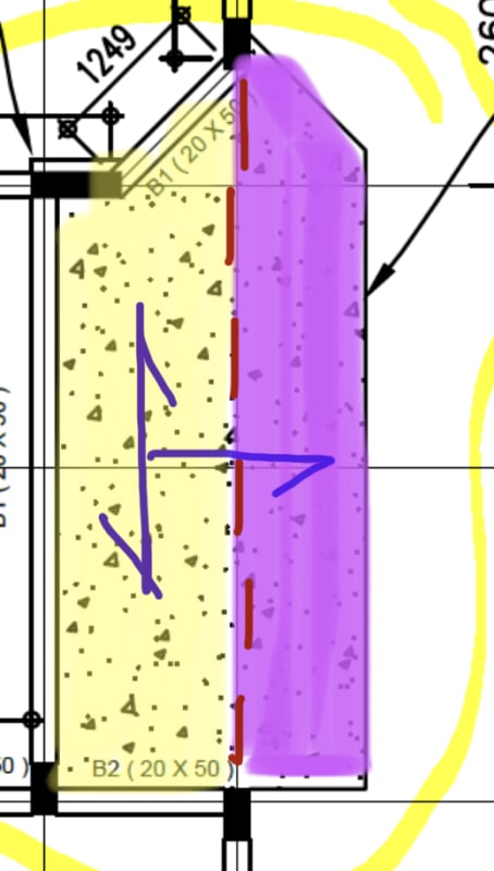
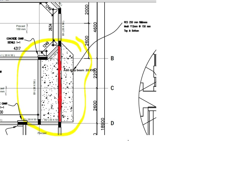
We have a 250mm thick in-situ concrete slab with 3-sided supports, and 1-sided cantilever. However, I am concerned that the slab does not have a backspan, as the rest of the villa is constructed using hollow-core slabs. I would appreciate your advise on how we could possibly develop the rebars sufficiently to develop the necessary rigidity in the beam/slab connection with minimal architectural changes.

Please refer to plan extract attached. Note that the beams are 500mm deep.

Thank you for your support.


 https://files.engineering.com/getfile.aspx?folder=c4ab6f19-293a-4446-9adc-9574418d91c3&file=V1PlanExtract.PNG
Replies continue below

Recommended for you

1) it'll be tough to meaningfully engage the precast deck given that the plank spans perpendicular to the intended balcony cantilever direction.

2) If possible, I'd try to make the slab work with just the three sided, simple supports, relying on no back span action.

3) if the hollow core plank has a topping and the elevations work out favourably, you might run some balcony top steel over the first couple of planks and into the topping as a redundant, belt and suspenders measure.
 
I'm not big on FEM for slab design, but I think the problem presented is one for FEM analysis... I think the 10" slab with 1/2" bars @ 6 T&B seems pretty robust for the 2.2 and 2.6m spans... but a tricky slab to analyse... The 10" slab will possibly span the 4.8m, but the effect of the cantilevered part is a little uncertain without doing some serious calculations. There would likely be uplift on the beams and maybe the precast may be of some assistance.

Looking at it again, I'd check to see if 1/2 the width of the 10" slab and reinforcing could span the 5+m (col to col) supporting the total load... and then treat the transverse slab as a cantilever about the line joining the columns... just as a first 'kick at the cat' if this is more than ample, I'd be happy with it... if more than 70%, I'd go a lot deeper into it.


Do you know how it was initially analysed?

Rather than think climate change and the corona virus as science, think of it as the wrath of God. Feel any better?

-Dik
 

Unless they contributed to weight, I would not likely consider them at all... just cloud the problem...

Rather than think climate change and the corona virus as science, think of it as the wrath of God. Feel any better?

-Dik
 
Edit: When the slab is modeled in 3-directions with pin joints only, it seems to be unstable in the FEM software (I'm getting ridiculous deflections)
 
That's not a stability issue; it's an exaggerated deflection diagram. You need to find the magnitude of the deflection.

Also tell us how you modelled the slab and what load (ultimate or serviceability). I assume uncracked, short-term properties but tell us the relevant details. Pretend we know nothing about your structure and analysis except what you tell us.
 
If it would be architecturally palatable, one solution would be to run a beam across the balcony recess.
 
I’d be surprised if you couldn’t get it to work as shown below by hand.

Hopefully my crappy sketch is self explanatory.

5EC358C8-705F-4C74-AA38-EB1E80937FB4_tamtvt.jpg


Ps - the dashed line isn’t a beam. Just a delineation between two slab span directions. It would work with an FE analysis in my view.
 
@Steveh49: The magnitude of the deflection is ridiculous (23400mm) when the joints are pinned. The section is uncracked, the analysis is linear elastic at short term properties. FYI, SDL = 3kN/m2, LL = 2kN/m2. Concrete cube strength is 35N/mm2, rebar yield strength = 460N/mm2.
@KootK: I thought about that but as you said, its not fitting with the architecture.
@MIStructE_IRE: You mean design the yellow slab as 1-way (North to South) and the purple would be cantilevered off that slab?
 

SDL = 3 kN/m2 so the total DL = 0.25*25+3=9.25 kN/m2 is this true ?

My suggestion will be use drop beam and reduce the thickness of cantilever to 150 mm. Proposed beam shown with red below..
V1PlanPROPOSALExtract_gvz8ld.jpg
 
Note, when you do FEM analysis, you shall check the restrain of the join that representing the columns. Restrain the rotation about the vertical axis will help to obtain a better result.
 
Check the inputs to the analysis. The supported edges don't seem to move so it isn't unstable as a rigid body. Hard to diagnose across a forum but look at section properties/dimensions (left off a zero? Millimetres vs metres?); Young's modulus and shear modulus (same); loads (same); accidentally pinned all nodes in the slab span rather than just the supports? Etc.

How does it deflect if you delete the cantilever area?
 

As noted above, the 1/2" high strength bars @ 6"o/c top and bottom could help...

Rather than think climate change and the corona virus as science, think of it as the wrath of God. Feel any better?

-Dik
 
Are those B1 beam 200 mm x 500 mm? If the slab is cast monolithically with those beams, I would see little difficulty. Moving the bottom edge to align with the inside of the beam would help.

But that doesn't account for bearing of the precast slabs. Maybe the beams need to be widened to accommodate both the precast slabs and the balcony.
 
@Steveh49, Tomfh, dik: Thanks to your input, I decided to recheck the modeling and it does look like it was a modeling issue. I isolated the slab separately and defined line springs to simulate the beam, and it looks like its safe structurally but the deflections are a bit on the high side.

I'll revise to 300mm thick or place the beam in the middle as others suggested.

Thanks for your input everyone.
 

realistic deflections? also long term deflections?... if you can add a beam, that's the easiest and you may be able to use a 150 slab...

Rather than think climate change and the corona virus as science, think of it as the wrath of God. Feel any better?

-Dik
 
@dik: The problem with the beam is that it won't fit with the architectural elevation (it's going to be in the middle of a recessed entrance area, no false ceiling).

When using 300mm thick slab, using same applied loading for Fcu = 35N/mm2, then:

* Deflection from linear analysis, with inertia modified to effective moment of inertia (using ACI-318 method)= 2.8mm (SLS case, assuming 100% of live load conservatively)
* Calculated long term deflection modifier = 1.733
* Long term deflection = 1.733 x 2.8 = 4.85mm
* Allowable deflection = L/480 = 2800/480 = 5.8mm

Consequently, the slab design is ok provided bottom rebar is increased to 16mm @ 150mm to suite ULS requirements.
 
...understood... it's just easier. Looking at the issue, it doesn't seem to be that difficult to solve. I'm a little surprised that the slab increases in thickness, but I haven't run any numbers. Your reinforcing appears to be 'heavy' but great for deflections.

Rather than think climate change and the corona virus as science, think of it as the wrath of God. Feel any better?

-Dik
 
Status
Not open for further replies.

Part and Inventory Search

Sponsor