Continue to Site

Eng-Tips is the largest engineering community on the Internet

Intelligent Work Forums for Engineering Professionals

  • Congratulations cowski on being selected by the Eng-Tips community for having the most helpful posts in the forums last week. Way to Go!

440x10x42x8H - DIN5480 2

Status
Not open for further replies.

andregtoledo

Mechanical
Nov 30, 2015
1
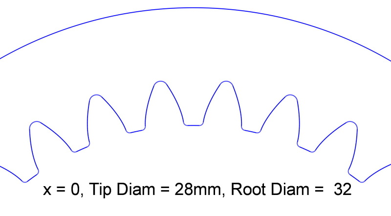
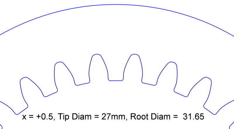
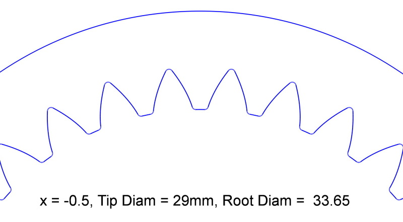
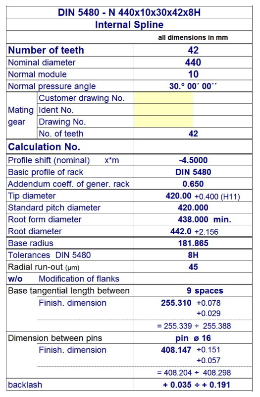
We need to manufacture a hub with these information: 440x10x42x8H - DIN5480

How can we tell from this if any addendum modification was used in the calculation of tip circle diameter and root circle diameter?
This will determine the calculation for the diameters of out hub will it not?

All help is appreciated.

Regards
Andre Toledo
 
Replies continue below

Recommended for you

Almost all DIN splines use the addendum modification, to achieve the reference diameter (440 mm in your case).
Reference dia is always larger than the outside diameter of the shaft; it describes "what you can safely, with enough clearance, slide over the shaft".
But you'll need much more info than just the addendum coefficient. The H7 is the tolerance/precision grade of your spline. It defines most tolerances for the hub. Their values/calculations are in the standard. You really should buy it.

Because it is almost Christmas I'll answer your question: per my DIN 5480 dated Oct. 1991, the addendum modification (x*m) for your spline is +4.5

Your part will be an expensive product; be sure that you verify all the dimensions including their tolerances - and again - you need that standard to do it properly!
 
gearguru said:
Because it is almost Christmas I'll answer your question: per my DIN 5480 dated Oct. 1991, the addendum modification (x*m) for your spline is +4.5

Almost right!
As the OP's question is about a hub; X*m = -4.50mm.
Seems obvious but someone that doesn't understand might have made a mistake.
 
Gearcutter, isn't the positive shift always moving the tool to a larger diameter? With splines to properly mesh you need to do it for both, shaft and hub or am I wrong?
 
gearguru said:
Isn't the positive shift always moving the tool to a larger diameter?

A good question, you've really made me have to think about this.

For internal gears or splines; I would say that what you're suggesting is incorrect.
For example; if I'm gear cutting an annulus which has a positive x applied to the profile, then the disc shaper cutter I'm using will need to be offset in a direction which is closer to the centre of the part. So the generated PCD (as well as the operating PCD) of the part ends up being smaller than if there were no x correction applied.

I could post some images if that'd help.
 
Per the standards/books which I have, the positive shift on the external gear/spline increases the tooth thickness and it can happen only if the tool moves away from the center of the external gear/spline.
The profile of the internal spline's tooth space has to be the same as the profile of the tooth of the external splines, plus, obviously the clearances.
I do not want to argue, I just do not want to confuse the OP.
Some explanation about using the profile shift is in this article (it applies to gears):

 
gearguru said:
I do not want to argue

It's a shame that you feel that way, as I thought we were having a meaningful discussion where either of us might learn something.

I've been cutting gears & splines for over 18 years now and in all that time I've never seen an internal profile of any sort, gear or spline, that has been designed with a + correction. I'm not saying that a + corrected internal doesn't exist, I'm just saying that it's not common.

I don't have time to read your article, but using software I did get a chance to create some images showing what I'm trying to explain.
The images show that entering a + correction to an internal gear gives a tooth profile with smaller tip & root diameters.

Also; for internal tooth profiles, AGMA2001 defines x as positive when the reference generating rack is shifted out of the material of the gear [towards the centre of the part] resulting in an increased tooth thickness of the gear teeth. -

x_0_Tip_Diam_28mm_Root_32_f3l4a5.jpg


x_0.5_Tip_Diam_27mm_Root_31.65_ntjydg.jpg


x_-.5_Tip_Diam_29mm_Root_33.65_wdgudi.jpg
 
The directional definition for internal gearing (x = positive --> tooth thickness increases) is also what i understand to be correct.
But then, as per the referenced above standard DIN 5480 part 1: inversion of the sign of the profile shift depending whether it's shaft or hub: pls. see attachment.
This is, because in order to get a systems of equations which could be run on a computer, all of the calculation values (diameters etc.) of an internal gear are changed to negative sign.
So finally, DIN 5480 part 1 states that in order to get correct and unambiguous manufacturing data, parts 3 to 13 contain diameters and measurement values for shafts and hubs (pressure angle 30°) --> For such a valuable item as per OP, pls. get the standard & also the counsel of smbdy competent in the procedures.

Regards


Roland Heilmann
Lpz FRG
 
 http://files.engineering.com/getfile.aspx?folder=7785efb6-2057-4746-98a3-5cfcf2196c35&file=5480.png
Such things need a defined rule, and the rule in all the systems and standards I have ever seen was: +x is moving the tool out of the material, -x is moving the tool in the material. There may be other rules, but certainly not in the case of DIN5480.
 
So to be clear then, for the sake of the poor OP, is it agreed that applying a negative profile shift on an internal involute profile will result in larger tip & root diameters? This will in turn, for a spline profile, produce a profile in the hub that will mate correctly with a shaft which has had a corresponding but positive profile shift applied to the profile.

I feel we've hijacked the original post so to help clear-up any confusion that the OP might have; here is all the data needed to manufacture the hub as per the DIN5480 standard.


Clip_4_t19odz.jpg
 
Gearcutter, you are right. What confused me was the fact, that I someway omitted that the internal spline/gear tooth is shaped as the external spline/gear space. Therefore moving the tool cutting the internal gear toward the center increases the tooth thickness.
I feel exactly as you-we wanted to clarify the issue. You did it, thanks!
And thanks to the others, who reminded me that in DIN standards even the number of teeth when calculating the internal gears properties has to be used as a negative number.
It would be nice to hear from OP...
 
gearguru said:
the internal spline/gear tooth is shaped as the external spline/gear space. Therefore moving the tool cutting the internal gear toward the center increases the tooth thickness.

That's a really good way of explaining it.
Glad to see that we're on the same page with this.
 
Status
Not open for further replies.

Part and Inventory Search

Sponsor