Continue to Site

Eng-Tips is the largest engineering community on the Internet

Intelligent Work Forums for Engineering Professionals

  • Congratulations waross on being selected by the Eng-Tips community for having the most helpful posts in the forums last week. Way to Go!

3D Beam element nodes deflection and stress calculation

Status
Not open for further replies.

magnum123456

Industrial
Nov 22, 2015
4
Hi all,

I am wirting a c++ program to calculate 3D beam elements deflection and stress, like the following picture:
p1_wb94l6.jpg

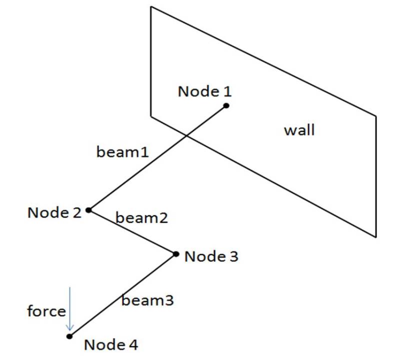
I have defined the stiffness matrix and calculate by the formula [stiffness matrix][d]=[F].
There are 6 dof in each node including 3 deflection and 3 rotation.
My program can solve the [d] for each node, and my question is how to use the [d] to find out the stress in each node? I have found many document about FEA but cannot find a concept about this. Hope anyone can help me.
 
Replies continue below

Recommended for you

You use the [d] to calculate the [F} at each node, then use that to calculate the stresses at any point on the cross-section.

In your case the structure is statically determinate, so you have the [F] already, but in a non-determinate structure you need to calculate the [d] first, so you can get the [F] for each member.

Doug Jenkins
Interactive Design Services
 
Thanks Jenkins,
for [stiffness matrix][d]=[F],like the picture example, my calculation is:
1. each beam matrix has 12 [d] and 12 [F],
2. combine the matrix to form a global matrix, result in 48 [d] and 48 [F],
3. solve the 48 [d] by the known 48 [F],

"You use the [d] to calculate the [F} at each node, then use that to calculate the stresses at any point on the cross-section."
Do you mean when I get the 48 [d], I should substitute each 12 [d] in each beam matrix to solve each 12 [F], and then calculate the stress?
If it is true, how to use the [F] to calculate the stress? Could you show me the formula as I am so confused by the stress formula of FEA indeed..

 
For example, at Beam 3, Node 3 you should have:

A bending moment about the horizontal axis
A shear force in the vertical direction
Axial force, horizontal shear force, bending about the vertical axis, and torsion should all be zero.

So you calculate the stresses in the section due to the bending moment (for the axial stresses) and due to the shear force (for the shear stresses) using the normal beam analysis procedures.

Doug Jenkins
Interactive Design Services
 
Jenkins,
this is what I am confused. Node 3 has no any external force, so how can I know the bending moment,shear force, axial force and torsion in the node 3.

 
make a free body diagram for element 3 ... the only way to react the applied load is with an internal shear force and moment at node 3. However, this is solving the problem with our eyes rather than with your math.

read up on the finite element method, internal strain energy. these concepts allow you to determine internal stresses from displacements. I suspect it has something to do with inverting the matrix you have for determining displacements.

another day in paradise, or is paradise one day closer ?
 
yes, now I only have a formula [stiffness][d]=[F] in my program, and is able to solve the displacement of nodes for different beam frame structure. What my target is to find another formula which is to solve the stress of nodes, then I can complete my program.

Thanks Jenkins, the link is so informative and I really need some time to understand all of it.
 
Status
Not open for further replies.

Part and Inventory Search

Sponsor