Haha, well 2*LF vib has always been of interest to me and moreso recently. So I took the opportunity above to explore some things that have been on my mind about 2*LF which I’m sure is not what the op was looking for.
For the benefit of OP, I’ll summarize the two most commonly cited sources of 2*LF from the literature:
1 – asymmetric airgap (static eccentricity)
2 – deformation of the stator core caused by the rotating fundamental mmf wave
I think above is a reasonable summary, and anyone wanting a 50,000 foot view should stop ….
=== WARNING RAMBLING IN-THE-WEEDS AHEAD ===
Since the thread is probably otherwise dead and I’m on a roll and enjoy talking about this (maybe it’ll bring out some comments I can learn from, or maybe one or two people will be interested in what I’m saying), I’m going to use this thread to explore some more thoughts and experiences about 2*LF vibration, focusing on the 2nd of the two 2*LF causes above which we didn’t talk about yet. I would argue the 2nd one is a common cause of 2*LF which often cannot be corrected and can form the basis for foot-sensitivity of 2*LF vibration.
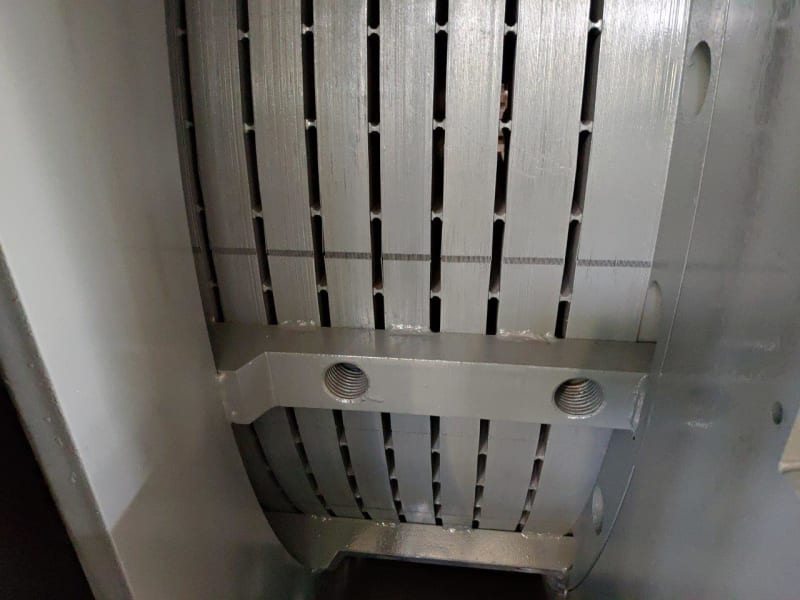
What do I mean by “2 - deformation of the stator core caused by the rotating fundamental mmf wave”? You’ve probably seen pictures of it before. It applies even when rotor is perfectly centered. For a 2-pole motor, the stator core is bent into something like an oval shape rotating at 3600rpm in 60hz land, so two peaks per revolution (of stator field) pass a given point and if you had an acceleromter on that point you’d see 120hz. If you have a 4-pole motor, the stator core is bent into a shape like a smooth 4-tooth gear. With field rotating at 1800rpm, you again see 120hz motion at a given point on the stator core. This is said to be a more prevalent vibration source for 2-pole motors because the arc width of the 2-pole is longer so it is less resistant to bending in that shape than it would be to bending into a 4-pole / 6-pole etc shape.
The vibration appearing on the stator core from this rotating stator core deformation can be different (higher) than what appears at the bearing measurement. Example
CURRENT AND VIBRATION MONITORING FOR FAULT DIAGNOSIS AND ROOT CAUSE ANALYSIS OF INDUCTION MOTOR DRIVES by William Thompson in proceedings of the 31st turbomachinery symptosium
Just under figure 9, you'll see they measured the stator core back-iron at two locations and saw
2*LF vibration was 4.5 times as high on the core as on the bearing housings.
It might be surprising for to you to learn above that the 2*LF vib is higher on that stator core is higher than on the bearing housings. To understand why that can occur, a few things to consider… First remember the electromagnetic force we’re talking about are acting directly on the stator core. Second let’s remember that this particular version of 2*LF (from rotating deformation of the stator core) is not accompanied by any unbalanced magnetic pull on the rotor. So it doesn’t load the bearings and won’t show up on the bearing housing that way. The only other way for the vibration to show on the bearing housings is by interaction between stator core and stator frame, which in turn holds the bearings. So exactly how does the core interact with the frame?
[ol A]
[li]On a large horizontal sleeve bearing motor, that interaction is typically minimal… the core is often bolted to the bottom of the frame and not rigidly attached to the sides, so the stator core can vibrate without transmitting that vibration to frame which holds the bearing housing.[/li]
[li]On a typical smaller NEMA frame horizontal motor things are more variable and trickier. I was told by an old Siemens motor engineer that it is an important part of the frame design that they keep the core deformation forces from causing vibration at the monitored location of the bearing housings. That is a challenge when you think about it, how is the frame which is supporting the core and intimate contact not going to move from those core forces. He said there were various frame design “tricks” that they use to accomplish that. He also mentioned that some TEFC motors of a cheaper design where the core was interference fit into the frame without ribs accomplished the desired suppression of bearing housing 2*LF in a non-robust way which was very sensitive to the interface pressure generated by the design interference. BUT if there were minor distortion from a soft foot, it effectively changed the carefully selected interface pressure/geometry and destroyed the optimization which they had designed specifically to hide the 2*LF from the bearing housings. In other words, a soft foot condition caused an increase in 2*LF vibration on these motors NOT because the airgap was distorted but because it altered their sensitive design in a way that allowed the 2*LF originating from rotating stator core deformation forces to appear on the bearing housings.[/li]
[/ol]
Blasphemy you say, everyone knows the airgap gets distorted by a softfoot and that what causes the common foot-sensitive 2*LF vibration on 2-pole NEMA frame motors. But how much does soft foot really change the airgap? I would say the stator frame has orders of magnitude higher bending resistance (bending moment of inertia) than the foot. Think about a 100hp 2-pole horizontal motor... Let's say the feet are maybe a 3/4” thick by 3” wide bar, whereas the stator frame might resemble something like a 1/2” thick cylinder of diameter 18” (already waaay stiffer as a calculation would easily prove... bending moment inertia of a hollow cylinder proportional to Diameter^4 vs beam proportional to thickness^4 with different coefficient but the factor [18/0.75]^4 dwarfs the difference in coefficient) plus a bunch more metal around the bottom and possibly more supporting structure inside. So the foot is going to do most of the bending, not the stator frame. Ruling out stator frame bending... maybe soft foot causes the endbell bolts to stretch or the endbells to got repositioned/distorted to a point that the rotor bends? First of all I don't see how that happens without the stator bending. Second of all I would point out there is some misalignment play in the bearings so there is not even any bending moment on the rotor until you exceed that play in the bearings. So my best guess is that any change in airgap from tightening a soft foot is going to be a small fraction of the foot movement. And by the way foot movement to affect 2*LF can be very low…. 0.002” is a typical acceptance criteria but I have seen feet with less deviation than that (as measured by feeler gage all around the interface between foot and base) which still show the foot sensitivity of 2*LF vibration.
Aside from my guesses about how much soft foot can affect airgap, an enterprising motor engineer on maintenanceforums.com tried to measure it as discussed here
and in attached article
"Deformation of airgap due to soft foot" . His conclusion was that the change in airgap was small and not enough to affect 2*LF vibration. I posted this info on another forum and there were some critiques of the measurement methods. It’s not an easy thing to measure on a NEMA frame motor (generally only larger motors have ports for this purpose). If I were going to do it I’d look for a suitable motor that has access all around the airgap from the end even with the motor assembled. We have a couple of horizontal open DRIP proof motors that have access to check airgap through the vent ducts, but only at the bottom half of each endbell. Maybe there is an OPEN (not dripproof) motor that has access to the airgap all around the circumference (anyone who has access to such motor feel free to try it and let us know).
So in my opinion, the soft foot doesn’t change the airgap much. You may or may not be convinced of that fact, but there’s more…
I have an anecdote from my experience at our plant that is somewhat relevant.
[ul]
[li]In 2003, we ordered seven 100hp 2-pole Open Drip Proof (ODP) motors from a motor OEM factory that happens to be nearby, with a specification that they had to pass our vibration requirements during testing while rigidly bolted down. (That requirement is different than the general NEMA vibration testing spec which allows them to be tested on a rigid or resilient mount… but I would strongly encourage everyone to include that requirement unless you are prepared to be surprised when that motor is run rigidly bolted down for the first time ever... at your plant!). The OEM was used to testing this size motors on a flexible pad, but accepted our rigid spec and expressed confidence they would meet it. When we got to the factory test, they seemed very surprised to see high 2*LF (0.2ips+) in the horizontal direction on their motors bolted down during the test run. The vibration went away with foot loosening, but the spec required rigidly bolted so they had to meet it. They tried three different motors and same results. They spent several days trying to fix it, by getting the airgap perfect (even sleeved and rebored some of the endbells). They planed the motor feet. They moved it to another test stand. I think they even drove it at a different speed with vfd to check for resonances. None of it worked, the 2*LF didn’t decrease very much through all these efforts. They were working under the assumption that the 2*LF must have been coming from airgap asymmetry and their efforts to resolve that did not change the foot-sensitive 2*LF in this case at all.[/li]
[li]Then they had a phone call with an engineer at a remote location overseas. They informed me they were going to cut some slots in ribs between the motor frame and the core (I think this construction ribs between frame and core is more common for ODP than TEFC). They didn't permit me to watch exactly what they did, saying it was some kind of secret. I came back the next day for the run and the 2*LF was almost gone (<0.02 ips I think). Their modification had worked. Trimming the rib between frame and core had fixed the foot-sensitive 2*LF vibration when no amount of centering effort had fixed it. I don't remember if they told me at the time or not but I came to understand that what the modification had done was to somehow change the characteristics of transmitting the force from the core to the frame to the bearings.[/li]
[/ul]
So far just an anecdote, why should you believe me. Recently I came across a reference which bolstered that view that trimming the ribs changed the characteristics of transmitting the force from the core to the frame to the bearings. Figure 11 in
UNDERSTANDING THE VIBRATION FORCES IN INDUCTION MOTORS by Michael J. Costello in Proceedings of 19th Turbomachinery conference shows a modification where the ribs between the frame and core were modified for exactly this reason. The caption includes
“To limit the transmission of the 120 Hz vibration from the stator core, each of the six ribs were notched as shown in the cross section. This tends to isolate the core from the end frame to which the bearing housings are mounted”. That gives a little insight why it works: the force is transmitted between core/frame gets limited by the modification to a region more in the center of the stator. That reduces the influence on the endbells/brackets which hold the bearings. It seems to be the same thing type of that was done on my seven motors in 2003. Most importantly it is also a direct in-writing acknowledgement of the types of design “tricks” that OEMs may use to try to prevent the vibration / forces from the core from reaching the bearing housing where they would be measured as mentioned by that old Siemens engineer.
Before I leave the subject I want to clarify what I'm NOT saying. I'm not saying #2 above is the cause of all observed 2*LF vibration on bearing housings, nor and I saying that 1 and 2 combined the explanation for all observed 2*LF. Rather, 2*LF is the fundamental frequency of electromagnetically generated forces throughout the machine and we should not be surprised if there are a variety of different ways that it can show up on the bearing housing.
My rambling has come to an end. Maybe it sounds like a half baked combination of anecdotes, links, 2nd hand stories and half-analysed suppositions designed to convince you of a conspiracy theory? If so, all I can say is that I’m not trying to convince anyone of anything, I'm just a man in search of the truth sharing all that I have...my collection of anecdotes, links, 2nd hand stories and half-analysed suppositions ;-)
Any comments?
=====================================
(2B)+(2B)' ?
")