madeinta1wan
Mechanical
- May 30, 2016
- 1
Hello Eng-Tips,
First post.
Helping a friend to remove a cast iron drive shaft that has some missing teeth on a coupling and wondered if someone might know how this bearing is assembled (and disassembled)
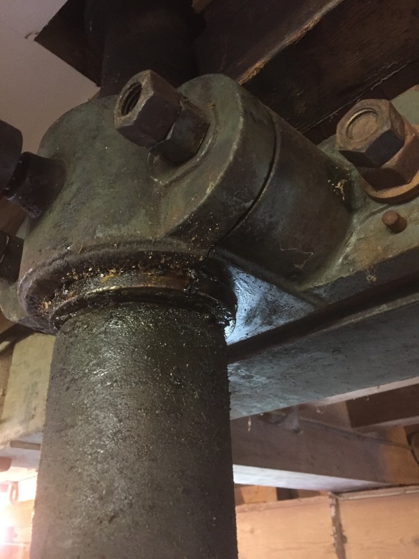
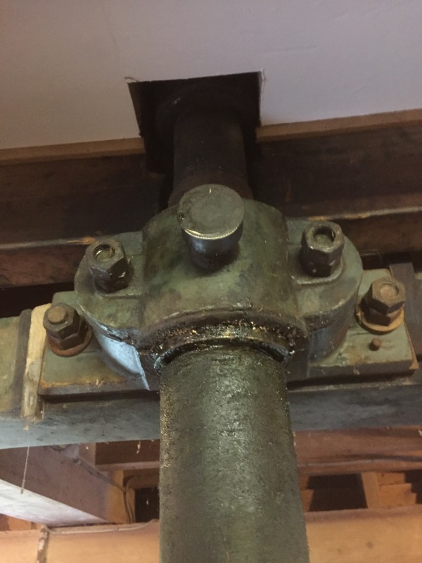
Within the plate that has a grease fitting on the face theres a lower and upper brass bush that looks to me like it couples the shaft to the next shaft going up out of the photo.
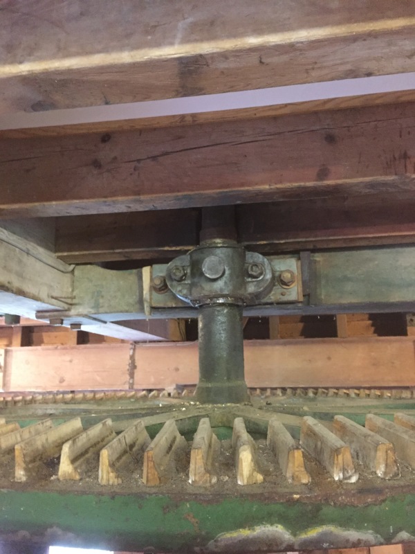
The shaft at the base has some broken teeth in that we've had remade and will weld back onto the shaft when it is free. Currently the shaft presses down onto the shaft below it and is kept parallel with a shaft coupling (pictured). To me it seems that the assembly of this mechanism happened from the ground up and the drive shaft and gear that we are trying to move may have been pushed into the bearing housing and the next shaft above it fitted in with a similar type of toothed alignment/drive fitting.
The question I have is is anyone familiar with this type of bearing/bearing housing? I've taken the front plate off and I can see two brass bushes and a steel/cast iron segment in between.
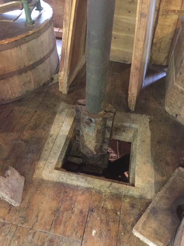
If I were to lift the shaft and gear slightly allowing the base of the shaft to be disconnected and pulled out of concentric alignment with the shaft below, could the shaft and gear be lowered physically or is there some bolted/mechanical connection with that bearing assembly that centuries of grease is preventing the shafts from coming apart.
Thanks,
Nate
First post.
Helping a friend to remove a cast iron drive shaft that has some missing teeth on a coupling and wondered if someone might know how this bearing is assembled (and disassembled)
Within the plate that has a grease fitting on the face theres a lower and upper brass bush that looks to me like it couples the shaft to the next shaft going up out of the photo.
The shaft at the base has some broken teeth in that we've had remade and will weld back onto the shaft when it is free. Currently the shaft presses down onto the shaft below it and is kept parallel with a shaft coupling (pictured). To me it seems that the assembly of this mechanism happened from the ground up and the drive shaft and gear that we are trying to move may have been pushed into the bearing housing and the next shaft above it fitted in with a similar type of toothed alignment/drive fitting.
The question I have is is anyone familiar with this type of bearing/bearing housing? I've taken the front plate off and I can see two brass bushes and a steel/cast iron segment in between.
If I were to lift the shaft and gear slightly allowing the base of the shaft to be disconnected and pulled out of concentric alignment with the shaft below, could the shaft and gear be lowered physically or is there some bolted/mechanical connection with that bearing assembly that centuries of grease is preventing the shafts from coming apart.
Thanks,
Nate