Continue to Site

Eng-Tips is the largest engineering community on the Internet

Intelligent Work Forums for Engineering Professionals

  • Congratulations waross on being selected by the Eng-Tips community for having the most helpful posts in the forums last week. Way to Go!

1.4 - fundamental rule (o)

Status
Not open for further replies.

AndrewTT

Mechanical
Jul 14, 2016
261
(o) - Dimensions and Tolerances apply only at the drawing level where they are specified. A dimension specified for a given feature on one level of drawing is not mandatory for that feature at any other level.

Example: I have a machined casting that has many as-cast surfaces remaining on it. These as-cast surfaces are important for proper part function. Based upon fundamental rule (o) I need to put these casting dimensions on the machined part drawing or they can be modified during machining and the machined part is acceptable even though the important as-cast surfaces have been detrimentally changed. That is how I read fundamental rule (o).

How do people handle this situation? Do you actually put all remaining as-cast surface dimensions on the machined part print (in duplication of what is already on the casting drawing), making the machined part drawing extremely complicated to read? Or, do you put a note stating that as-cast surfaces are not to be modified from the casting print during machining?

Thank you.
 
Replies continue below

Recommended for you

AndrewTT,

I have done very few castings. If I do a machining drawing of a casting, I would show any interesting casting dimensions for reference. As per ASME[ ]Y14.5, they would be shown in brackets. The machine shop would have no control over these, and I can see no reason why the shop would take the time and effort to modify them.

--
JHG
 
AndrewTT - I think you are misunderstanding thing.

You don't normally repeat dimensions on subsequent drawing levels except for reference or things like datum targets etc.

In your example of a machining drawing for a casting - they are only to do the machining required to meet the machining drawing requirements. They should not be arbitrarily machining or otherwise modifying other features etc.

You normally only dimension the features at the level they are created (and as required inspected).

These features are then only modified at subsequent levels if you are explicitly told to do so.

"Or, do you put a note stating that as-cast surfaces are not to be modified from the casting print during machining?"

Is hence not required.

Posting guidelines faq731-376 (probably not aimed specifically at you)
What is Engineering anyway: faq1088-1484
 
AndrewTT, my experience with machining castings (for valves) is 2+ decades old, but machining fixtures will need some place to consistently located the part. We frequently machined them in two steps, the first to add locating surfaces, the second to add the machined part features. If this is the case for your parts you may need to specify which areas are ok to add locating features too (you should discuss this with the fixture & machining people) or specify which areas must not be altered.

Just my experience. Diego
 
It's common to supply the casting drawing, for reference, to shops machining them. It's not mandatory, but it sure is helpful. For reference only.

I have always worked, and dictated work be done, similar to KENAT's clarification. The machined-part-drawing is specifying the "scope of work" which is not only what the machine shop /shall do/ but also limits them to do /only these things/ unless authorization is approved (such as tooling holes/features for setup/fixturing that do not inhibit part function)
 
I appreciate the feedback. So, if I am misinterpreting 1.4 (O) then what do you guys read it to mean exactly?
 
I have always interpreted it very simply and literally as-stated. In this example, the machine shop is bound to supply all the machined features IAW the drawing requirements. The casting supplier is responsible for supplying castings that conform to the casting specifications and drawings. The machine shop is not responsible for the as-cast features, nor should they be, as they have no control over them. If you were to place as-cast dimensions on the machined-part drawing without stating that they are for reference only, then you are placing unnecessary requirements upon the machined part supplier. Reference dimensions are handy, though, in lieu of actually supplying the casting print for reference.

I've always used examples in discussion such as bolted assemblies. If an assembly calls out for the use of a 1/2-13 UNC Shoulder Bolt, Part Number 'X', I am only requiered to supply that component. I am not required to verify or modify any dimensions of that part, or to ascertain the dimensional requirements and inspect it.

There may be a drawing modifying a standard 1/2-13 UNC Shoulder Part, Part Number 'X', however, and it may have no dimensions other than a diameter dimension on the head. It is likely that the machinist must supply that Part Number 'X' Shoulder Bolt, with a reduced-diameter head, possibly by turning on a lathe. So long as it began life in my shop as Part Number 'X', the rest is moot. I must only complete the reduced diameter called out on the drawing. Just because there's a drawing of those other features somewhere else, dictating the size, form, and tolerances, does not mean they apply to my drawing, to which I'm contractually bound to adhere to.

That's common practice in my experience. Only modify what you're told to do on the drawing, and ensure conformance to everything on the drawing. That's always been my interpretation.
 
It's the tricky thing - viewing the drawing as manufacturing instructions versus the drawing as documenting inspection acceptance requirements.

If viewed as the former, then there is no way to account for part deformation due to material removal. One cannot add a requirement to the machining drawing that will check to see that as-cast (for example) features remain unchanged within the original tolerances. Instead, the out-of-tolerance condition will not be detected until after the part is put into production and might end up in delivered products, potentially requiring a recall, possibly doing great harm.

As an inspection document, the machinist will review the drawing, do only the work required, and the inspector will verify the part meets all the requirements on the drawing. If the part fails on a feature the machinist doesn't affect, then the part does not enter the supply chain. Instead the engineering team is called in to determine why the feature that passed at the casting supplier no longer does. The result may be that the casting needs to be stress relieved or it could be that the machinist needs to not bend the part in a fixture (I've seen both.)**

What makes the processing of castings difficult is that, against the advice of the standard, the casting drawings are used to specify the manufacturing method. "The drawing should define a part without specifying manufacturing methods."

Essentially, there should not be a separate casting drawing; only a finished part drawing that might include sloped surfaces and mismatches that accommodate the process or just have really large profile tolerances.

However this is inconvenient for purchasing because they can't find a cast/machining supplier and so it becomes an engineering problem to solve the contracts issue.

To turn this another way - if an engineer wants to use an off-the-shelf part that happens to be cast and then machined and needs to ensure that it will fit, do they create two envelope drawings or just one that encompasses all the surfaces, as-cast and machined alike?

** The best/stupidest was when a part was being probed for compliance on the CNC machine and it passed, but then could not be assembled because the fixture put so much load on the part it twisted. When it was removed from the fixture it twisted back to it's original, free-state shape. I guess if the assemblers could use a 30 foot prybar they might have gotten it installed; who knows.
 
Just wondering...

3DDave said:
One cannot add a requirement to the machining drawing that will check to see that as-cast (for example) features remain unchanged within the original tolerances. Instead, the out-of-tolerance condition will not be detected until after the part is put into production and might end up in delivered products, potentially requiring a recall, possibly doing great harm.

Couldn't the following symbol be used on the machining drawing and applied to the surfaces that must remain unchanged within the original tolerances?

capture_o7iuyj.png


3DDave said:
Essentially, there should not be a separate casting drawing; only a finished part drawing that might include sloped surfaces and mismatches that accommodate the process or just have really large profile tolerances.

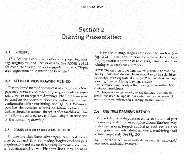
Not saying this is incorrect, but seems like in contradiction to what's been stated in section 2 of Y14.8-2009.

capture1_wxyi3m.png
 
Sure you 'could' do that, just like you 'could' put the OP's suggested note, but I don't believe it's required.

Posting guidelines faq731-376 (probably not aimed specifically at you)
What is Engineering anyway: faq1088-1484
 
So if not the symbol or a note, what on the drawing would technically protect the as-cast surfaces that must remain unchanged from being "detrimentally changed" by subsequent machining process?
 
pmarc - the part you took out of context is based on my observation of the typical argument that dimensions and tolerances should not be duplicated from the casting to the machining, not that it's impossible to tell the machinist to leave a surface alone. Even if the machining doesn't carve into a surface, that doesn't prevent the part from warping due to relief of internal stress or because of over-enthusiastic clamping.

'14.8 is dedicated to the concept of supporting purchasing convenience, so it is obviously not going to say 'don't make drawings per this standard' even though it could be entirely absorbed as a chapter of special application into Y14.5. The 'don't machine this' should be in the main standard and used to apply to purchased parts that are modified, rather than being trapped in a casting standard.
 
I did not mean to take it out of context. My apologies.

We do quite a lot of machined casting drawings, and from my experience the approach preferred by Y14.8 is not only for purchasing convenience.

FYI: I didn't take the 'don't machine this' symbol from the casting standard - it is in Y14.36 for surface texture symbols. But in general, I agree some of the concepts/techniques shown in Y14.8 probably should be absorbed by Y14.5 - just like the movable datum target symbol was in 2009.
 
pmarc, should the engineering part acceptance drawing represent the end product or should the package be broken down into manufacturing steps?

As I posed before, if you were buying another manufacturer's off-the-shelf part that happened to be cast and then finish machined by that manufacturer, would that be represented by one envelope drawing or two?

I get the convenience when more than one fabricator is involved, but that is a purchasing problem, even if it is all in-house. Two different cost groups will be involved.

One way I know this is a problem is that often there are discussions back and forth about how much material has to be globbed on to a casting just to have enough material to machine off. Why is it necessary or useful to require an inspection on material that will be turned into chips? That should be up to the manufacturing engineers to determine what they need and generate a manufacturing process drawing in concert with the casting supplier. Change the supplier and the process drawing is changed - no change to the engineering documentation, no ECRs, no ECOs, just like when telling how big a piece of plate a part will be milled from.

When I was doing tolerance analysis (so sad to lose VSA) I kept getting hit with the machining/casting divide. One item that was particularly vexing was due to the complexity of the shape and the amount of post-cast post-heat treat straightening. Rather than controlling the overall shape of the part, the engineers at QA insistence**, opened up the tolerances to the point where unusable parts would be accepted. To avoid that happening, they added a note that the casting was to be 'optimized' relative to some post-casting post-straightening spot faces and pin holes.

These magically appeared in the part by using a pre-machining simulation fixture where each area built up in anticipation of being machined was compared with an offset simulator and was manually checked for suitable potential cleanup using a feeler gage, thereby completely divorcing all other features from the 'optimum' frame of reference.

As they played with the process they finally managed to create a massive interference at the final assembly, an interference that could not be predicted with tolerance analysis because there was no quantifiable limitation on the variations of the bosses that were eventually machined based on the optimizing spot faces/pin holes and the optimizing was divorced from all other cast surfaces.

Had the finished part requirements been on the machining drawing, including profile limitations on the cast surfaces and the casting supplier been pushed to provide a machinable casting, no defective parts would have made it to the factory floor.


**In this company the factory floor had ultimate veto power. If a part didn't fit they would try to alter that piece part and then demand a drawing change to retroactively accept the the out-of-spec part. If an engineer pushed back, the engineer would often be black-balled for holding up production. Deviations and Waivers were seen as accusing manufacturing of making mistakes and they controlled the change board and certainly could not ever be at fault. Once black-balled, an engineer would be unable to do further work and end up no longer working. Yes - grinders on the assembly line and a final trip to the paint booth to cover installation related, changes were the norm.
 
Perhaps the following will be of some interest:

ASME Y14.24-2012 para. 8 said:
Modifying drawing types are altered item, selected item, and modification drawings. These drawing types are not used for items made from raw or bulk materials, items purchased in bulk lengths (e.g., extrusions, channel nuts, hinges, etc.), or such semiprocessed items as blank panels, castings, electronic equipment drawers, etc. For such items, use detail or detail assembly drawings. See sections 5 and 6, respectively.

ASME Y14.24-2012 para. 5 said:
A detail drawing provides the complete end-product definition of the part or parts depicted on the drawing. A detail drawing establishes item identification for each part depicted thereon.


pylfrm
 
Those definitions seem to leave casting drawings as semi-processed (manufacturing process) drawings. It seems the context of 'for such items' is items that are made from raw, or bulk, or semiprocessed items, not the items themselves, as a contrast to altered item, selected item, and modification drawings that apply to items that are not made from things on that list.
 
3DDave,

First of all, my apologies for late response.

I guess different people/organizations prefer different approaches depending on circumstances. In the company I work for there are at least a couple reasons why casting and machined casting drawings are done as separate documents. These include, but are not limited to, the following:
- different suppliers make castings and machined castings for us;
- in many cases, either casting or machined casting drawing contains information that shall not be available for the other supplier (one of the reasons is key technology control);
- castings have very specific quality requirements that can be examined only when the part is in as-cast condition;
- with the use of end item drawing approach, there is no robust way to control stock allowance for surfaces that are subsequently machined off. This may lead to unexpected mechanical properties of the end item (as stated in para. 4.2 in Y14.8) - for example when the stock allowance is close to absolute minimum. This may also lead to machining cost increase - if the stock allowance is too generous much more material needs to be machined off (cycle time increase, etc.).

In general, I agree that the drawing should specify the end product without breaking it down into manufacturing steps. However - as stated in the fundamental rule 1.4(e) in Y14.5-2009 - there may be exceptions to that. People way too often like to read only first two sentences of that paragraph without digesting what the rest of the paragraph is about. In my opinion, there is enough reasons to say that separate casting drawings provide information that "is essential to the definition of engineering requirements".
 
I get why people do it. At the end though, the finished part is the finished part no matter how it got there and the drawing really should depict that condition.

If there's a need for process control drawings, that's what should be made, not pushing manufacturing detail requirements back onto the engineering and acceptance document. Sure, in the rare case where IP is so valuable you can't trust partners, then do whatever it takes to keep them in the dark.

I take 'essential' as covering those conditions where it is impossible or impractical to determine in the finished part that some characteristic has been met. For example, some parts are sensitive to the amount of chlorine in rinse water, which is difficult to determine during fabrication and too late by the time it gets to inspection.

Going back to an off-the-shelf item - does a Source or Spec control drawing of a machined, cast item include the machining allowance in a separate casting drawing? Anything is possible, but it seems like it should be as often for these parts as directly designed parts.
 
I haven't done many castings & forgings but I've done enough to believe you're better off with separate drawings.

Even supplier that does their own subsequent machining finds having the 2 separate drawing system easier and asks for that.

Posting guidelines faq731-376 (probably not aimed specifically at you)
What is Engineering anyway: faq1088-1484
 
Hi Kenat,

Of course it's easier. For them. It's only noticeable when there is significant dependence on the location of cast features to machined features and to neighboring parts. For most of the castings I've seen there's a lot of clearance around the cast features so the variability doesn't get noticed.

But on some, like the castings I analyzed where there was very little clearance and the drawings were split up with cast features not getting their dimensions and tolerances repeated on the machining drawing, this approach ended badly.

In a related notion, I have wondered if there was any CNC software that could probe all the cast features that are going to be machined as well as all the clearance surfaces and determine an linear and angular offsets to minimize the amount of cleanup time while meeting any surface layer removal minimum requirements.

In addition to the variability due to straightening, the in-house shop people often failed to clear the chips from the fixtures so we ended up with goofy compound tolerances like dia 0.250 on the upper and dia 0.015 on the lower relative to previously precision machined datum features to account for the chip pile. This variation would back-drive the casting .125 in various directions relative to the cast surfaces on top of the amount put there when the datum references were placed.

It seemed to me the software could skip the middle step and cope with the chip piles and locate the all the features based on comparison with one frame of reference.

It's been a while and I haven't seen this level of adaptability so I assume most places know how to use a brush to clean the fixtures or don't design multiple intermeshed castings that get bolted together. Or they just spend more on their casting straightening than they would if they could more easily cope with that type of variation.
 
Status
Not open for further replies.

Part and Inventory Search

Sponsor