Hello all,
New to the timber world and I am basically self taught in everything, but i am curious in how you would go about analyzing a small span bridge with timber poles for a "max load".
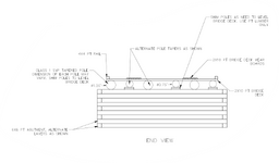
I have attached a sketch of what I am thinking about building
I say small span as in 22' clear span I am thinking.
are the cross sectional areas of each pole able to be added together during bending analysis? assuming the load is distributed accordingly (which I know is probably not the case as the inner poles would carry more then the 2 outer, but this is for general discussion)
Again this is just for my general knowledge and discussion, however when built these bridges will be used for agricultural purposes so it would be nice to have an idea as to what a producer can traverse this bridge with as they have some heavy equipment sometimes and timber is generally the way to go around here as cost is a huge driver
Again this is just a general question on how you would approach the analysis for the system with multiple members acting together
cheers
G
New to the timber world and I am basically self taught in everything, but i am curious in how you would go about analyzing a small span bridge with timber poles for a "max load".
I have attached a sketch of what I am thinking about building
I say small span as in 22' clear span I am thinking.
are the cross sectional areas of each pole able to be added together during bending analysis? assuming the load is distributed accordingly (which I know is probably not the case as the inner poles would carry more then the 2 outer, but this is for general discussion)
Again this is just for my general knowledge and discussion, however when built these bridges will be used for agricultural purposes so it would be nice to have an idea as to what a producer can traverse this bridge with as they have some heavy equipment sometimes and timber is generally the way to go around here as cost is a huge driver
Again this is just a general question on how you would approach the analysis for the system with multiple members acting together
cheers
G