Tek-Tips is the largest IT community on the Internet today!

Members share and learn making Tek-Tips Forums the best source of peer-reviewed technical information on the Internet!

  • Congratulations MintJulep on being selected by the Eng-Tips community for having the most helpful posts in the forums last week. Way to Go!

Fatigue Test of Metal Parts

lLouie

Student
Joined
Jun 19, 2024
Messages
82
Location
EU
Hi,

As is well known, not every part of an aircraft is subjected to the same g-forces. I have previously opened many topics related to fatigue testing, and thanks to your help, I’ve achieved very good results. First of all, I would like to thank all of you.

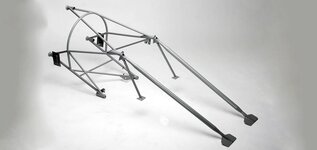
As I mentioned, different parts of the aircraft are subjected to different g-forces. Attached, I’ve shared a structure from the aircraft. For example, this component is rated for a maximum of 5g. I want to perform a fatigue test for this part, but I’m unsure about what the loading conditions should be. Should I apply a constant amplitude test between 1g and 5g? I believe the fatigue test should be different from those conducted for the wing structure.

I checked the standards, but couldn’t find any specific information on this. Could you please help me with this?
 

Attachments

  • aircraft-engine-mounts.jpg
    aircraft-engine-mounts.jpg
    30.7 KB · Views: 3
5G is the ultimate (or limit) static design load ... on the airplane (loads that are almost never experienced in real life). This will produce a bunch of loads (including aero, so talking inertia loads isn't complete or accurate) on the structure.

Fatigue loads are not static design loads, but in-service loads, typical operational loads. These are not defined by standards, though ACs will have information on how to set spectra. A severe operational load may be a 3G manoeuvre ... and the attendant aero loads. It is generally conservative to have a fatigue spectrum of 1 limit load cycle per flight
 
Seems to me that the fatigue loads would have something to do with how the plane and its structure flexes over different flight phases and the time spent in those phases.
 
5G is the ultimate (or limit) static design load ... on the airplane (loads that are almost never experienced in real life). This will produce a bunch of loads (including aero, so talking inertia loads isn't complete or accurate) on the structure.

Fatigue loads are not static design loads, but in-service loads, typical operational loads. These are not defined by standards, though ACs will have information on how to set spectra. A severe operational load may be a 3G manoeuvre ... and the attendant aero loads. It is generally conservative to have a fatigue spectrum of 1 limit load cycle per flight
Firstly, thank you for the answer.

In order to perform a fatigue test on the component, it is essential to acquire the in-flight g-load data acting on the part. However, different flight configurations may result in varying g-load profiles. For example, during one flight the load may fluctuate between 1g and 1.5g, while in another it may range from 1g to 2g. Should these loads be applied using a constant amplitude approach?

Specifically, if I select the most critical flight case, would it be appropriate to conduct a fatigue analysis and test using a constant amplitude load cycle between 1g and 2g? Or should I instead apply the actual random load spectrum recorded during that particular flight?
 
Seems to me that the fatigue loads would have something to do with how the plane and its structure flexes over different flight phases and the time spent in those phases.
You are right.
The most critical aspect is to accurately determine these loads and understand how they should be applied. Various configurations may occur in the aircraft, each potentially leading to different loading conditions.
 
fatigue is about capturing the generalities of the operation with enough detail (and tolerance) that specific usage is reasonably captured. OEMs classify the operation of their plane with several configurations and mission descriptions ... a limited set of conditions so they can crunch the numbers. They then check with the operators to validate these assumptions (as being reasonably accurate at capturing fleet usage). Military operators can delve deeper, into Individual Aircraft Tracking, as individual planes can do significantly different operations.

With your plane, make a conservative assumption. I would recommend getting your structure loads for 1g on ground, 1g inflight and 2g inflight. Now you can derive the "delta 1g inflight" structure loads (substracting 2g inflight from 1g inflight). Now you can create a detail fatigue spectrum for different structural elements ... a flight profile like 1g on ground > 1g inflight > 2g inflight > 1g inflight > 1g on ground; ... ok, this is a start !?

Now you can modify this all you want (there is no standard, there are tomes written about how to do what I've described in a couple of paragraphs) ... the flight above has 1 2g manoeuvre, you can change this to multiple manoeuvres, manoeuvres with different load factors, maybe add a landing impact ? You can create a spectrum using different flight types (1 flight with 2g, 9 flights with 1.5g, ... ad nauseum) ... the idea is to have something you think is reasonably conservative.

But this is a student forum, and this topic is way too complicated to adequately discuss in this manner. I think you said this is a kit plane project ? I forget where you said you are located.

"
This is a project. I have such a task and I'm searching. I know that there is no any standard. Aircraft can have many mission profiles. For example, I observed that the aircraft was exposed to 2g loads during a mission, and I tested it accordingly. What will happen if the aircraft experiences 2.2g even once in its lifetime?
 

Part and Inventory Search

Sponsor

Back
Top