Tek-Tips is the largest IT community on the Internet today!

Members share and learn making Tek-Tips Forums the best source of peer-reviewed technical information on the Internet!

  • Congratulations TugboatEng on being selected by the Eng-Tips community for having the most helpful posts in the forums last week. Way to Go!

Weld Size Calculation for Plate Welded Perpendicularly to RHS Beam

nevo2011

Mechanical
Joined
Jun 12, 2025
Messages
2
Hello everyone,


I’m working on a welded connection between a rectangular hollow section (RHS) beam and a flat rectangular plate.
The RHS is fixed on one end, and on the other end, a flat plate is fillet-welded around its perimeter (full weld) to the open face of the RHS.


The flat plate is intended to be pulled downward, perpendicular to the beam’s axis – generating axial tension on the plate and corresponding load on the welds.
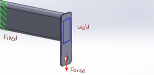
1749720480493.jpeg

I’m looking for guidance on how to calculate the minimum weld throat size required in this configuration.
 
Force / (2 x throat x effective weld length of one vertical weld) <= allowable yield.

Give or take some of the national parameters like allowances on material values, weldments, safety factors.

Don't count on the horizontal welds.
 
If you have a steel manual, equations are given in Chapter J section 4.

Like kingnero said, don't consider the horizontal welds, only consider vertical welds. This is a conservative approach.

First, required force for each weld needs to be calculated. This can be as simple as dividing Force by 2.

Then the allowable force for each weld needs to be calculated. From AISC 360 ChJ.4, if using LRFD, phi*Rn = 1.392*D*l, where D is the weld size in sixteenths of an inch and l is the length of the weld. This assumes FEXX = 70 ksi for weld strength.

Finally compare required and allowable forces and see if the weld passes. If it doesn't, the weld size D can be increased.

To fully check the weld, the base metal must also be considered. Here is a video that may help:
 
I don’t know how significant this is, but don’t forget that the beam bends, resulting in rotation at the free end. The rotation and the length of the plate will result in a horizontal offset between the point of load application and the N/A of the beam at the free end, causing a moment.
 
Force / (2 x throat x effective weld length of one vertical weld) <= allowable yield.

Give or take some of the national parameters like allowances on material values, weldments, safety factors.

Don't count on the horizontal welds.

If you have a steel manual, equations are given in Chapter J section 4.

Like kingnero said, don't consider the horizontal welds, only consider vertical welds. This is a conservative approach.

First, required force for each weld needs to be calculated. This can be as simple as dividing Force by 2.

Then the allowable force for each weld needs to be calculated. From AISC 360 ChJ.4, if using LRFD, phi*Rn = 1.392*D*l, where D is the weld size in sixteenths of an inch and l is the length of the weld. This assumes FEXX = 70 ksi for weld strength.

Finally compare required and allowable forces and see if the weld passes. If it doesn't, the weld size D can be increased.

To fully check the weld, the base metal must also be considered. Here is a video that may help:
I tried what you said, and when I want to compare it to the answer that SolidWorks calculated for me, there is a difference of almost 3 times even more.
Is there perhaps an explanation why?, The problem is very simple, there is nothing too complicated here
 
I tried what you said, and when I want to compare it to the answer that SolidWorks calculated for me, there is a difference of almost 3 times even more.
I did forget to factor in the sqrt(3) as the weld's in shear, not tensile.

Force / (2 x throat x effective weld length of one vertical weld) <= allowable yield / sqrt(3)

SolidWorks probably will assume the entire perimeter to be resisting the applied force (which is not completely untrue).
I can't explain the times 3 diff.
 
Your standard fillet weld formula is found in chapter 8 of the AISC manual. In my blue version, it's equation 8-1. You can get a decent strength bump if you account for the load angle with the equation on the next page. Just add up the capacity of the parallel and perpendicular welds. Things get a bit more complicated if you have moment on them, which it doesn't look like you do. Figure 8-6 gives you a bare bones list of the basic shapes. You can use parallel axis theorem to build any shape you want from those. Stress = Moment / Section modulus. Then you need to check the bolt bearing (J3.10, block shear (J4.3), and then tearout for the hole (J3.10).
 

Part and Inventory Search

Sponsor

Back
Top