Continue to Site

Eng-Tips is the largest engineering community on the Internet

Intelligent Work Forums for Engineering Professionals

  • Congratulations Ron247 on being selected by the Eng-Tips community for having the most helpful posts in the forums last week. Way to Go!

Simple yield line question

canwesteng

Structural
May 12, 2014
1,730
I'm having a brain fart here, and no one in my office is terrific with yield lines. Normally I take the yield line mechanism of a flat plate (fixed support in this case) to be the red line, with the diagonals at 45 degrees. However, the project length about the horizontal of the diagonal yield lines decreases the steeper they get and the vertical projection doesn't change. So the steeper these get the weaker the mechanism, though this seems irrational. It is simple to just call the diagonals 45 degrees in the case of reinforcement equal in each direction, but in this case the short side has less reinforcement than the strong side, so it must be somewhat steeper than 45. Is there something I'm missing?
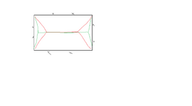
Untitled.png
 
Replies continue below

Recommended for you

What is your go-to reference for learning/worked examples for this? No one in my office uses yield line theory, but it's something I'd like to learn.
I have been retired since 2008, so my go-to reference may be a little out of date. I started to use Yield Line Theory in the early 1960's. My reference was "Reinforced Concrete Fundamentals" by Phil M. Ferguson. I expect there have been more recent articles on the subject since then, but I can't recommend any in particular.
 
Well in an isotropic material, the yield lines will be symmetric, and if the supports are symmteric, you'll just end up with 45 degree angles.
I agree that the yield line pattern is symmetric, but you will not always end up with 45 degree angles, even if the material is isotropic. It seems to me that as the length to width changes, the angle will change.
 
I agree that the yield line pattern is symmetric, but you will not always end up with 45 degree angles, even if the material is isotropic. It seems to me that as the length to width changes, the angle will change.
It might always be 45 deg but I would need to see a reference that demonstrates that.
 
It’s not necessarily always at 45 degrees. Things don’t even really fail like that in practice. Those 45 patterns are just assumed failure patterns that are close enough to how slabs and plates fail.

If the material is anisotropic it will tend to go more towards a one way failure mode.
 
It might always be 45 deg but I would need to see a reference that demonstrates that.

Ferguson used a trial and error method shown below. He found point O to be 8', 7' and 7.5' from the left edge in three subsequent trials. That suggests the angle is not 45 degrees, but using his criteria, I found the dimension to be 6.75'. If the angle is 45 degrees, it should be 6', half of the 12' dimension of the slab.

It seems to me that a better solution, which avoids multiple trials is to equate the external work in slab A and B, then calculate the ultimate load of the slab.

When the length to width becomes much larger, I am not convinced that the Yield Line Method produces believable answers, but I would need to spend a bit more time on it to convince myself otherwise.

1748901591010.png
 
I did try some with isotropic material, and in the end, it isn't 45 degrees, it's something like 44 degrees. So the 45 degrees only holds for squares.
 
I did try some with isotropic material, and in the end, it isn't 45 degrees, it's something like 44 degrees. So the 45 degrees only holds for squares.
I agree that the slope of the yield line is dependent on the aspect ratio of the slab, but for a 12' x 20' slab, I would have expected the difference to be greater than one degree. I am going to have to check my calculations. Unless I made a mistake, the diagonal yield lines slope at 6/6.75, or an angle of 41.6 degrees from the long edge.

I will have another look at it.
 
I neglected critical tasks this afternoon and spent time working out the solution to this situation. The curiosity got the better of me.

Attached are my calcs. They have not been checked by anybody else but me, so use at your own risk. Also, if anybody sees an error, please let me know!

Looks like the angle varies from 30 deg. to 45 deg. With an aspect ratio of 2.0, the angle is 37.5 deg.
 

Attachments

  • Rect PL, SS, Unif Load, YLA.pdf
    139.5 KB · Views: 26
I neglected critical tasks this afternoon and spent time working out the solution to this situation. The curiosity got the better of me.

Attached are my calcs. They have not been checked by anybody else but me, so use at your own risk. Also, if anybody sees an error, please let me know!

Looks like the angle varies from 30 deg. to 45 deg. With an aspect ratio of 2.0, the angle is 37.5 deg.
This math looks like fun, time to jump down the rabit hole of virtual work.
 
This math looks like fun, time to jump down the rabit hole of virtual work.
At least I avoided a bunch of algebra and calculus mistakes by using Mathcad. Ha.

I did one manual calculation with numerical values and it agreed with my computerized calcs, so I feel pretty good about it.

I would be interested in knowing if it matches any textbook solutions. I don't seem to have one that's simply supported and isotropic.
 
Last edited:
Very nicely presented, 271828. So we know that the angle of a diagonal yield line is not always 45 degrees to the long edge when the rectangle is not a square. For an aspect ratio of 20/10 = 2, you found the slope to be 5/6.51, or an angle of 37.5 degrees to the 20' edge.

The ultimate load turned out to be 565.6 psf using yield line theory (an upper bound theory). The plastic moment was assumed to be 4000'#/' in all directions. Taking the ultimate capacity of a 10'x20' two way slab without any contribution of corner levers, wu = 4000*8(1/100+1/400) = 400 psf, which is only about 70% of the yield line value. That may be reasonable, but there is no guarantee that deflections will be acceptable in either case.

For concrete slabs, my preference is to use a lower bound solution. I suspect that most engineers would consider a slab with an aspect ratio of 2 as a one way slab. I know I would. Adding steel in the short direction is more effective than using equal amounts in both directions.
 
Last edited:
I neglected critical tasks this afternoon and spent time working out the solution to this situation. The curiosity got the better of me.

Attached are my calcs. They have not been checked by anybody else but me, so use at your own risk. Also, if anybody sees an error, please let me know!

Looks like the angle varies from 30 deg. to 45 deg. With an aspect ratio of 2.0, the angle is 37.5 deg.
I couldn't digest this entirely - but I ran my own check and also got the same answer except with 37.5 degrees being from the vertical line and not the horizontal one. I think that makes more sense - the wider the plate the closer it comes to just folding in the middle.
 
I couldn't digest this entirely - but I ran my own check and also got the same answer except with 37.5 degrees being from the vertical line and not the horizontal one. I think that makes more sense - the wider the plate the closer it comes to just folding in the middle.
The aspect ratio should be 20/10 = 2, not 0.5 as I incorrectly stated in an earlier post, but the 37.5 degree angle is measured from the long side, namely 20'. In the calculation by 271828, distance 's' was 6.51' and the half width of slab was 5' , so the slope is 37.5 degrees from a horizontal line.

That makes sense because if the slab had been square in plan, work by gravity would be equal in segments #2 and #3. Segments #1 would not exist and yield lines would be at 45 degrees. When the slab is rectangular, dimension 's' must increase to compensate for segment #1 which has been added in the central region. Segments #3 increase in area and their c.g. moves further from the edge of slab, so 37.5 degrees is the angle between the 20' edge and yield line.
 
Last edited:
I neglected critical tasks this afternoon and spent time working out the solution to this situation. The curiosity got the better of me.

Attached are my calcs. They have not been checked by anybody else but me, so use at your own risk. Also, if anybody sees an error, please let me know!

Looks like the angle varies from 30 deg. to 45 deg. With an aspect ratio of 2.0, the angle is 37.5 deg.
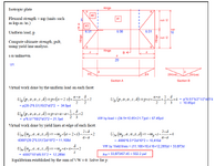
I used the 's' value of 6.51 in the expressions for VW, and came up with a slightly different result for pultimate, but I may have made an error in the process. The blue text is mine. I agree that your method follows Yield Line Theory as I understand it, but I would never design a rectangular slab that way, particularly with an aspect ratio of 2 or more.

1749254095722.png
 
BARetired, thank you for going through that. It's great to have some interaction with these calcs because I think they're difficult. Please see attached. I have some comments in red. Please let me know if you agree or not. 271828
 

Attachments

  • BARetired271828YLACalcs.pdf
    133.9 KB · Views: 7
BARetired, thank you for going through that. It's great to have some interaction with these calcs because I think they're difficult. Please see attached. I have some comments in red. Please let me know if you agree or not. 271828
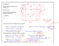
I do agree with your comments, and I am more than a little embarrassed at my own incompetence. My latest comments are in green.

I have reservations about relying on Yield Line Theory for concrete slabs, and I suspect that, in this case deflections would be unacceptable.
1749321629921.png
 
Incompetence. That's funny. These calcs are difficult IMO. I appreciate that you cranked through those terms!
 
Thanks for your contribution to this discussion, 271828. It is much appreciated.
 

Part and Inventory Search

Sponsor