Tek-Tips is the largest IT community on the Internet today!

Members share and learn making Tek-Tips Forums the best source of peer-reviewed technical information on the Internet!

  • Congratulations cowski on being selected by the Eng-Tips community for having the most helpful posts in the forums last week. Way to Go!

Design of Built-up section.

Wani_1

Mechanical
Joined
Apr 8, 2025
Messages
3
Hi, I was wondering what ways one would use to get an equal radius of gyration in both yy & zz axis of given cross sections.

I tried using 2 flat plates and I beam to achieve this by equating the desired radius of gyration to that of the highest radius of gyration of the I beam.
After some algebra, I got an uneconomical plate thickness (106mm).

Are there any other consideration made to achieve equal radius of gyration and reasonable thickness in my case?

Thanks.
 
so I imagine you have an I beam with two "vertical" plates closing the section, creating a box.

I assume you have a narrow tall I beam, as opposed to a short squat one. I think the flanges should be as wide as the beam web is tall ... it doesn't Have to be, but I is going to be mostly Aflange*height^2/2 on one side and Aplate*width^2/2 on the other ... rough and approximate ... so if you're getting a very thick plate, you need to increase the width.

why are you doing this (an equal radius of gyration in both yy & zz axis of given cross sections) ?
 
You've got 2 equations and 2 unknowns, assuming thickness is constant and the other dimensions are in multiples of t. Presumably you know how to calculate Iyy and Izz? parallel axis theorem and all that.
 
so I imagine you have an I beam with two "vertical" plates closing the section, creating a box.

I assume you have a narrow tall I beam, as opposed to a short squat one. I think the flanges should be as wide as the beam web is tall ... it doesn't Have to be, but I is going to be mostly Aflange*height^2/2 on one side and Aplate*width^2/2 on the other ... rough and approximate ... so if you're getting a very thick plate, you need to increase the width.

why are you doing this (an equal radius of gyration in both yy & zz axis of given cross sections) ?
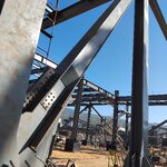
I saw this and wondered how such a beam was sized. I take it the goal was to eliminate the idea of having one strong and weak axis in relation to buckling?
If you take a look at the image below, the I beam doesn't seem that big.
 

Attachments

  • IMG_20250703_090404.jpg
    IMG_20250703_090404.jpg
    1.1 MB · Views: 6
You've got 2 equations and 2 unknowns, assuming thickness is constant and the other dimensions are in multiples of t. Presumably you know how to calculate Iyy and Izz? parallel axis theorem and all that.
My constant in my calculations was Plate height h limited by the gap between the I-beam flanges. The only practical dimension to vary was the plate thickness.
Lol I do know how to go about the calcs for Iyy and Izz, I went further and incorporated the web of the beam as well to help attain a smaller plate thickness. I suppose all I want to know is whether there are other factors I did not consider.
 

Part and Inventory Search

Sponsor

Back
Top