Tek-Tips is the largest IT community on the Internet today!

Members share and learn making Tek-Tips Forums the best source of peer-reviewed technical information on the Internet!

  • Congratulations cowski on being selected by the Eng-Tips community for having the most helpful posts in the forums last week. Way to Go!

DC Motor Drive - Imbalanced input (line/neutral) and output (motor + / - ) current 2

PaulKraemer

Electrical
Joined
Jan 13, 2012
Messages
158
Location
US
Hi,

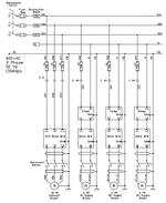
I am trying to troubleshoot a blower drive system that includes a DC drive board [KB Electronics KBCC-255 (9940A)]. The DC drive board controls a 0-180 VDC output to a DC motor that drives a blower. The magnitude of the 0-180 VDC output is determined by a 0-10 VDC signal that the DC drive board receives from a closed loop speed controller. There are three identical blower drive systems on the same machine. Each blower drive system utilizes the same components and is wired the same way. The attached image shows how these components are wired. The drives I am focusing on are the #1, #2, and #3 Supply Blowers.

All three Supply Blower drives were working fine for a long time, but the 15 amp fuse that protects the #2 Supply Blower drive recently started blowing repeatedly. The #1 and #3 Supply Blowers are still working fine.

We were able to get the #2 Supply Blower running by replacing the 15 amp fuse with a 30 amp fuse, and we took some current measurements with a clip-on ammeter while all three blowers were running.

On the #1 and #3 Supply Blowers (which are working fine), we measured very similar current on the line (going into terminal L1) and the neutral (coming out of terminal L2) in the input power circuit for the drive. We also measured very similar current on the output power wires to the motor, one coming from terminal A1 (+) and the other coming from terminal A2 (-).

On the #2 Supply Blower (which is misbehaving), we measured noticeably different current on the line and the neutral of the input power circuit. We also measured noticeably different current on the A1 (+) and the A2(-) output power conductors to the motor. Our exact measurements are shown below....

#1 Supply#2 Supply#3 Supply
Input Line Current1.32 amps16.5 amps5.4 amps
Input Neutral Current1.8 amps4.5 amps4.5 amps
Motor A1 (+) Current2.4 amps4.6 amps4.6 amps
Motor A2 (-) Current2.2 amps12 amps4.5 amps

When we took these measurements, #3 Supply Blower was running at a faster speed than #1 Supply, so the higher current does not surprise me. The seeming imbalance between line and neutral and A1 (+) and A2 (-) on #2 Supply does concern me.

If anyone here can give me an idea what might cause this, I would greatly appreciate it. I'd like to determine if the problem is more likely in the DC drive or external to the DC drive (perhaps the motor and/or the filter through which the input power circuit passes).

Any advice or suggestions will be greatly appreciated.

thanks in advance,
Paul
 

Attachments

  • BlowerDrives.PNG
    BlowerDrives.PNG
    54.4 KB · Views: 11
1) All three DC systems are NOT wired the same, according to the image appended. Units 1 and 2 take power from "Phase 2" to neutral; Unit 3 takes it from "Phase 3" to neutral. I suspect the Unit 1 connection was intended to be from "Phase 1" to neutral - it would be a good idea to physically verify the drawing to the reality.
2) The fuse(s) in question are on the incoming power line (L1 termination) which means they are monitoring the incoming current, not the "return" current. If the fuse is operating (i.e. "blowing") then something is making that particular system (i.e. Unit 2) draw more power - to the point where it overloads the protection.
3) The DC machines driving the supply blowers are presumably 2 HP at 180 Vdc (and some operating speed - likely in the 1800 rpm vicinity). This would give a rated current at full load in the 5.2 A range. As a result, Unit 3 motor is (apparently) operating at nominally 100% electrical load, while unit 1 is operating at roughly 35% electrical load. Unit 2 is ... well ... unit 2.

Question(s)
a) Where does the output air from each blower go? Do they act as a series path to the exhaust - or are they parallel?
b) has anything changed on the process side - such as a position change on dampers/louvers, etc. - that might allow recirculation between different fans?
c) what does a thermal image tell you about the temperature(s) of all three motors and all three "drives"? Are they nominally the same or different?
d) is there a different acoustic noise to the impeller connected to Unit 2 (e.g. rattling, whistling, screeching, etc.) that might denote a mechanical issue with the blower itself?
 
I suspect either a ground fault somewhere,
OR
Someone has grounded the neutral in one or more locations.
Look for the missing current on the protective earth conductor.
If you find the missing Amps on the PE, then try to follow the current back to either the drive or the motor, or possibly both.
You don't report the motor running hotter than normal so I expect a fault external to the motor.
Given that the motor currents are unbalanced, I would first look at the motor connections and look for a possible motor ground fault very close to the A2 end of the motor winding.
Depending on the brush arrangement, a brush lead may be shorting to ground.
 
Thank you Gr8Blu and Waross for your replies -

To answer Gr8Blu's questions:

(a) Each of these these three blowers take inbound air from a duct routed from the blower inlet to outside the building where the equipment is located. The blower outlet pushes air through two inline filters (one 95% efficient ASHRAE followed by a 99.99% Hepa filter). After the filters, the air passes through an electric duct heater before being routed into a supply inlet in a Drying Tunnel. This is a three zone Drying Tunnel through which a continuous web (with a coating that needs to be dried) is conveyed by roll-to-roll web handling equipment. Each blower (and supporting filter/heater assembly) delivers air into a dedicated dryer inlet (one inlet for each zone). The blower sizes, duct diameters, the filters, and the heaters are identical for all three blowers. There may be minor differences in the duct lengths for each blower due to their locations relative to the Drying Tunnel, but this machine has been working with 15 amp fuses without issue for over fifteen years until now. The Drying Tunnel has a single Exhaust Blower that removes the heated air from the entire dryer. So, I'd say the three blowers can be considered independent, except for the fact that a single exhaust blower is removing the combined air that all three supply blowers provide. The exhaust goes through a dedicated exhaust duct to outside the building, so there is no recirculation capability.
(b) I have no reason to believe anything has changed on the process side, but this machine is in India and I am in the USA. The last time I was at this site was in 2017. I am trying to help remotely.
(c) I do not know if the people I am supporting have the instruments to take a thermal image, but I will ask them if the supply motor #2 seems hotter than #1 and #3.
(d) They have not observed any unusual noise at Unit 2 that would indicate a mechanical problem. They also confirmed that with power off, they are able to turn each of the three blowers by hand (by turning the pulleys and belt that couple the motor to the fan.

Regarding Waross' suggestion - this sounds very plausible to me. This is going to make me sound ignorant, but I am much more familiar with delta power sources where there is no neutral. In an installation like this where there is a neutral, would you expect it to not to be grounded in any location? Or would you expect it to be grounded in exactly one location (presumably at the power source) to avoid ground loops?

I will ask them to measure current on the PE conductor. If they do find the missing current on this conductor, I am having a hard time envisioning how we could determine whether the problem was at the motor or the drive. The drawing shows the PE connector landed at the motor, the drive board, the filter, and then in the control enclosure where the drive and filter are located. If we measured current on the PE conductor and wanted to determine if the problem was the motor or the drive, would you recommend disconnecting the PE connector at different locations to see which location causes the PE current to stop? Or would you expect that without disconnecting anything, we might measure PE current only at certain locations in this PE circuit (close to the motor, close to the drive, or somewhere else)?

I did ask them to inspect the motor brushes, and they said they look ok.

I really appreciate your help.

Thanks again,
Paul
 
Or would you expect it to be grounded in exactly one location (presumably at the power source) to avoid ground loops?
Yes. Common practice and a requirement of most codes.
would you recommend disconnecting the PE connector at different locations
Yes.
First at the motor. Note, there may be an alternate ground path if the motor is mounted on steel connected to structural steel.
If the tech's have a DC clamp meter, measure the current in the PE conductor.
A long shot, disconnect the neutral at the motor and see if the motor still runs.
If any tests show ground conductor current at the motor, look for an inadvertent connection between the neutral and ground and check for an internal fault to ground in the motor.
Next. Do similar tests at the drive controller, only after the motor is found to be good.
 
The most likely cause, but not the only possibility:
Someone servicing the brushes accidentally caused a short to ground from one of the brush holders.
 

Part and Inventory Search

Sponsor

Back
Top