Hi everyone,
I’m working on modeling a bistable mechanism in Abaqus and am having trouble getting the hinge interconnection to work correctly.
Problem Summary:
When I run the simulation, only one of the shell parts moves while the other stays fixed, even though I have defined the hinge connection between them.
Setup Details:
Boundary Conditions:
Issue:
When the simulation runs, the moving part responds to the load, but the second part remains stationary, as if the hinge connection is not actually linking them.
Image:
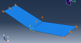
Below is a screenshot of the assembly setup:
(If posting on forums that do not support attachments, you can upload the image separately and include a link.)
Request:
Could anyone please advise:
Any help or suggestions would be greatly appreciated.
I’m working on modeling a bistable mechanism in Abaqus and am having trouble getting the hinge interconnection to work correctly.
Problem Summary:
When I run the simulation, only one of the shell parts moves while the other stays fixed, even though I have defined the hinge connection between them.
Setup Details:
- Element Type: S4R shell elements
- Geometry: 3D deformable planar shells
- Steps: Static General
- Assembly Workflow:
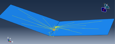
- Created datum points and converted them into reference points
- Translated and rotated the shell parts into position
- In the Interconnect module, created a line element connecting the reference points and assigned a hinge interconnection
- Specified a local coordinate system with the X-axis as the free rotation axis
Boundary Conditions:
- Initial step: Fixed side parts with U1 = U2 = U3 = 0
- Static General step: Applied displacement boundary condition to the middle part to induce deformation
Issue:
When the simulation runs, the moving part responds to the load, but the second part remains stationary, as if the hinge connection is not actually linking them.
Image:
Below is a screenshot of the assembly setup:
(If posting on forums that do not support attachments, you can upload the image separately and include a link.)
Request:
Could anyone please advise:
- How to correctly define the hinge interconnection so that both shell parts move together?
- Are there specific checks or constraints needed to ensure the connectivity is enforced during simulation?
Any help or suggestions would be greatly appreciated.