OffshoreWindStructures
Structural
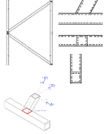
I'm looking at an accidental case in a 2d HSS frame that would result in load in the branch members for all 6 degrees of freedom (axial, torsion, major axis shear, minor axis shear, major axis bending, minor axis bending).
The members have the capacity for the combined load so the next question are the welded connections (k-joint and y-joint). Using matched sections (weld is a combination of flare bevel and fillet ) and beta=1 and b/t < 16 so connection in considered rigid enough to carry the moment.
Most of the examples i've seen focus on either axial only cases or axial and moment. I would like to compare some of my assumptions with examples that include torsion as well as axial, and in plane and out of plane shear and bending. Do you know of any such examples?
My assumptions are:
Axial load for branch = axial load for weld (considering the 1/sin(angle) transformation) = shear load in chord (with some axial)
in plane shear load for branch = in plane shear load for weld (considering the 1/sin(angle) transformation) = axial load in chord (with some shear)
out of plane shear load for branch = out of plane shear load for weld = out of plane shear load in chord (with some torsion)
in plane bending for branch = in plane bending for weld = in plane bending for chord
out of plane bending for branch = out of plane bending for weld = torsion for chord
torsion in branch = ?torsion ? for weld = out of plane bending for chord
My main question is : am i right in saying the torsion in the branch should also be transformed out of plane bending for the weld depending on the angle ?
My thinking is that If the angle was 90 degrees torsion in branch = torsion in weld and if the angle was approaching 0 degrees torsion in branch = out of plane bending for weld so it should be transformed.
do you have any examples of a fully loaded connection that involves a skewed member with a reference on the transformations for the weld?

