Continue to Site

Eng-Tips is the largest engineering community on the Internet

Intelligent Work Forums for Engineering Professionals

  • Congratulations Ron247 on being selected by the Eng-Tips community for having the most helpful posts in the forums last week. Way to Go!

Deciding the lateral force resisting system.

M_U

Civil/Environmental
Aug 11, 2024
10
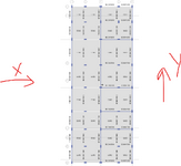
Hi, i got a building to review. The person is using special moment resisting frame parameters as per ASCE 7-16 for the x and y direction of the building. But as per the model, the engineer is not using beams along x direction in two bays due to the height restriction. They are relying on the assumption that the forces will be transferred through diaphragm which is 300 mm thick. The seismic design category of the building is D. I am suspicious about this configuration. I need guidance on how to approach this problem. Fist of all if this configuration is acceptable or not. If there is no beam to connect columns then can we rely on the slab to transfer the EQ forces. What will be changes in the detailing of the slab for this situation.

Thanks.
 

Attachments

  • 123.png
    123.png
    59.4 KB · Views: 34
Replies continue below

Recommended for you

I don't think they are assuming a slab-column moment frame in the two bays in the x direction.

I think they are relying on column-beam-column single bay moment frames for the x direction between bays 3 and 4.
 
The slab needs to serve the role of drag strut collector. Some assessment of the tension and compression capacity of the slab as a strut/tie needs to be performed. There are different approaches used, some add supplemental reinforcement while others use the slab distributed reinforcement over a specific width.
 
  • Like
Reactions: M_U
Yeah - the diaphragm isn't really spanning far between lines of support, there's definitely some simple calcs you could do to vet the diaphragm forces.
 
  • Like
Reactions: M_U
What will be changes in the detailing of the slab for this situation.

The slab to column joints should be, in some way, checked for the flexural punching shear induced by the drift of the moment frames.
 
  • Like
Reactions: M_U
Thanks for the insights. Can someone recommend any reference guide where I can look for this type of detailing and calculations.
 
This set up could be OK . I think the designer considered the frames only at 3rd and 4th bay . The orientation of the columns at axis 3.4. anf 5 could be studied and improved for better moment frame resistance .
 

Part and Inventory Search

Sponsor