Continue to Site

Eng-Tips is the largest engineering community on the Internet

Intelligent Work Forums for Engineering Professionals

  • Congratulations IRstuff on being selected by the Eng-Tips community for having the most helpful posts in the forums last week. Way to Go!

Axial pipe load - how is this transferred to the pad foundation

Anaheim

Geotechnical
Jun 3, 2025
9
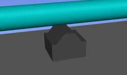
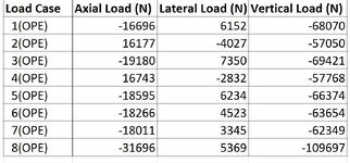
I have a query that I need some advice on. I am checking the bearing capacity of pad foundations supporting an above-ground pipeline. The pipeline team have provided loads, which include an axial load along the longitudinal axis of the pipe, a lateral load and a vertical load. The civil engineer advised me to apply an overturning moment caused by the axial load (lever arm of 1m) which causes a very large load eccentricity significantly reducing the effective breadth of the foundation. The pad foundations are typically quite small (1m x 1m x 0.5m deep) and therefore I am sceptical that the axial load would induce such a large moment. The lateral loads in the direction perpendicular to the pipeline are relatively small and are not an issue in terms of eccentric loading. Instead, would the axial load not transfer a frictional load to the foundation?

Any advice would be greatly appreciated.
 
Replies continue below

Recommended for you

Instead, would the axial load not transfer a frictional load to the foundation?

It would do both. But axial loads due to thermal expansion can indeed be enormous if you try to restrain them. Often, a reasonable approach is to avoid restraining them or, at the least restrain them in very strategic ways.
 
It would do both. But axial loads due to thermal expansion can indeed be enormous if you try to restrain them. Often, a reasonable approach is to avoid restraining them or, at the least restrain them in very strategic ways.
Unfortunately the piping team would not reassess their assumptions and loads. So is the civil engineer correct that the axial load would induce an overturning moment on the foundation? Some of the axial loads are so high that it becomes impossible to design the 1m x 1m x 0.5m sized foundations as the eccentricity exceeds 1/3 of the foundation breadth.

See below image of the pipe and the sleeper foundation
 

Attachments

  • Pipe sleeper foundations .JPG
    Pipe sleeper foundations .JPG
    52.7 KB · Views: 17
Last edited:
Anaheim --

Realistically what happens is that the thermal expansion does in fact generate that large overturning moment -- your effective breadth of the foundation diminishes significantly, and you apply a significant pressure to that reduced bearing area.

Right up until the point that the foundation compresses the subgrade, rotates as a rigid body, and the pipe support has moved as far as the pipe wants to expand or contract. Once that has happened, the axial load goes away, and so does your overturning moment.

If your subgrade can compress elastically in the range required, this can make the challenge significantly easier to address. If the subgrade will not respond elastically, then you may need to increase the foundation footprint accordingly.
Thanks for your response. I am proposing well-graded engineered fill for a nominal depth of 300mm from the underside of the foundation and then check that the load has spread sufficiently in underlying weaker soil. Using your rationale, do you ignore the eccentricity due to the overturning moment in the calculation and instead check that the soil can withstand the lateral movement elastically? Any idea on how to go about this check?
 
See below image of the pipe and the sleeper foundation

The aboveground pipelines are not restrained . That is , the pipeline should be designed to have sufficient flexibility such that thermal expansion or
contraction should not cause excessive stresses in the piping material or impose excessive forces on equipment or supports.

Your sketch is a simple sleeper and if it is scaled , it cannot restrain the pipeline either.
Short answer:
-The axial load should be the friction load developing along the pipeline,
Long answer:
- The pipeline engineer shall perform flexibility analysis, take necessary measurements to limit the axial stresses on the pipeline. ( if the lay-out does not provide sufficient flexibility, flexibility should be provided by the use of loops , bends, offsets). If you try to restrain the pipeline, you may witness that the sleepers subject to uplift, buckling problems..You may consider to provide more info.( pipe line plan , diameter , service , operating and ambient temperatures, etc) to get better responds.
 
Pipe supports in an axial direction can see loads from thermal expansion so the force is typically vertical load (weight of pipe and contents) x friction factor of 0.3 or similar.

Overturning of your design is commonplace and you normally need an upside down T shaped design.

I will be honest here and say that the design you posted to me is a poor design when you need to allow for thermal expansionand contraction of the pipe.

Especially in poor soils, seeing supports rolled over is commonplace.

You need to post some numbers here so that we can see if you mean normal expansion loads or whether these are restraint loads.
Thanks for your response. See attached loads provided for one of the supports. Loadcase 8 is a hydrotest load case.
 

Attachments

  • Loads.JPG
    Loads.JPG
    119.4 KB · Views: 15
Loadcase 1 - Weight of pipe including content and insulation + Maximum Design Temp
Loadcase 2 - Weight of pipe including content and insulation + Maximum Operating Temp
Loadcase 3 - Weight of pipe including content and insulation + Maximum Design Temp + Internal Design Pressure
Loadcase 4 - Weight of pipe including content and insulation + Maximum Operating Temp + Internal Design Pressure
Loadcase 5 - Weight of pipe including content and insulation + Minimum Design Temp + Internal Design Pressure
Loadcase 6 - Weight of pipe including content and insulation + Maximum Winter Temp + Internal Design Pressure
Loadcase 7 - Weight of pipe including content and insulation + Internal Design Pressure
Loadcase 8 - Weight of pipe including content and insulation + Hydrotest Pressure
 
That looks about right. It assumes you have some sort of movement in all cases, either thermal or contra tion from Poissons effect and a simple sliding support steel on steel so friction factor 0.3.

If this supports are simply set on grade then they will overturn if you get any significant movement.

Ask the team to also give you axial movement at each support.

If it's only say 5mm then the sort is fine. If its 25mm then maybe not.
 
Why are you not using a steel/steel or Teflon slide plate to limit axial load transmission to the supports?
 
Why are you not using a steel/steel or Teflon slide plate to limit axial load transmission to the supports?
Based on your experience, what would be the % reduction in the axial load transmission when using the side plate? It is something I can mention in the calculation report for the structural engineers to consider during detailed design
 
If this is an insulated pipe then it will have metal shoes.

Teflon can reduce the load but increase pipe movement.

Basically the support is the wrong shape.
 
The sleeper you show is just a sliding support. The only horizontal force is due to sliding friction when pipe thermally expands. The maximum horizontal friction load can only be the coefficient of friction times the vertical weight load of the pipe. For steel on steel (pipe on steel plate) the coefficient of friction is 0.3.

Fh = 0.3 x Fv Where Fh is the vector resultant of the axial and perpendicular horizontal loads and Fv is the vertical weight load of the piping on the support.

If your horizontal load is greater than 0.3 times your vertical load then there is a mistake somewhere.

For large horizontal friction loads typically spread footings are used sized so that the overturning moment due to friction is opposed by the resisting overturning moment of the footing.
 
I just saw that you had posted loads from piping stress report. Those look about right as the vector sum of horizontal forces is about 0.3 times the vertical load indicating the horizontal load is basically due to sliding friction.

In this case use spread footings designed to have an overturning resisting moment greater than the moment due to horizontal friction load.

As previously indicated use teflon pads to reduce horizontal load by 1/3. Teflon has coefficient of friction of 0.1.
 
Last edited:
You need to see what impact Teflon has on the piping movement. Sometimes it's good, sometimes it's not. Plus Teflon pads can wear out so it's not the conservative approach..

You generally need a ratio of 3:1 length over height where length is axial direction. Your support is closer to 1:1
 
I don't believe teflon pads have any effect on amount of thermal expansion except maybe on the order of thousanths of inch. Maybe teflon will wear over time if there is a lot of hot/cold cycling.
 

Part and Inventory Search

Sponsor