Daniel_LEE
Civil/Environmental
- Nov 11, 2024
- 7
Hi all,
I am simulating a RC beam under 4-point bending test and the results were terrible. I have attached the results below and I have three problems that I have no idea how to solve. I have been refining this model for the past few weeks. I could not resolve the problems and thus seeking help here. I would be really grateful if anyone could help me on this.
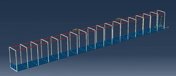
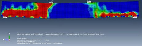
Model Description: I am building a reinforced high-strength concrete beam under 4-point bending test. The steel reinforcement includes ties, tensile bars with anchorage and minimum reinforcement bars at the compression zone of the beam. I have defined CDP damage parameter with relationship I have obtained by inserting concrete properties into an excel. I followed standard settings for interaction of the parts I have seen on YouTube. I used "embedded region" for constraining the steel bars and concrete beam. For the loading point and simple support simulation, I define them with steel material properties, used "general contact" as their contacts with the beam. I have then partition the support into half and applied boundary condition to the partition lines. For the loading, I have used "rigid body" constraints to tie the reference point to the loading plate and then applied point loads to the reference point.
The analysis took roughly 30 hours and has a total of 13811 increments. I am not sure if this is normal. The dimension of the beam is (3600x250x400) in mm.
The problems are as follows:
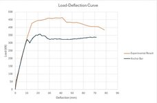
1) The load-deflection curve showed an earlier failure, approximately 100kN lower in ultimate strength, of the beam.
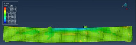
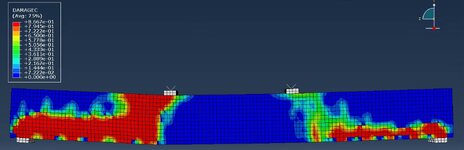
2 The bending stress distribution within the bending is not realistic. The results at the end of the analysis showed concentrated stress distribution around the loading point, where as the bottom of the beam where should experience the highest tensile stress only showed average stress values.
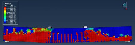
3) At the end of the analysis, the entire beam had cracks formed all over it. The result attached should indicate a beam that has been completely torn apart. which is not realistic and does not match with the experimental result. Even the compressive damage value is unrealistic.
I have tried to find the cause of these problems and specifically looked at the instant when failure of the beam started. Yet, I did not know how to interpret the results and thus had not idea how to proceed to resolve all these problems. I would be really grateful if someone could provide me with some advice on what to look into or share their experiences in modelling RC beam under bending.
I am simulating a RC beam under 4-point bending test and the results were terrible. I have attached the results below and I have three problems that I have no idea how to solve. I have been refining this model for the past few weeks. I could not resolve the problems and thus seeking help here. I would be really grateful if anyone could help me on this.
Model Description: I am building a reinforced high-strength concrete beam under 4-point bending test. The steel reinforcement includes ties, tensile bars with anchorage and minimum reinforcement bars at the compression zone of the beam. I have defined CDP damage parameter with relationship I have obtained by inserting concrete properties into an excel. I followed standard settings for interaction of the parts I have seen on YouTube. I used "embedded region" for constraining the steel bars and concrete beam. For the loading point and simple support simulation, I define them with steel material properties, used "general contact" as their contacts with the beam. I have then partition the support into half and applied boundary condition to the partition lines. For the loading, I have used "rigid body" constraints to tie the reference point to the loading plate and then applied point loads to the reference point.
The analysis took roughly 30 hours and has a total of 13811 increments. I am not sure if this is normal. The dimension of the beam is (3600x250x400) in mm.
The problems are as follows:
1) The load-deflection curve showed an earlier failure, approximately 100kN lower in ultimate strength, of the beam.
2 The bending stress distribution within the bending is not realistic. The results at the end of the analysis showed concentrated stress distribution around the loading point, where as the bottom of the beam where should experience the highest tensile stress only showed average stress values.
3) At the end of the analysis, the entire beam had cracks formed all over it. The result attached should indicate a beam that has been completely torn apart. which is not realistic and does not match with the experimental result. Even the compressive damage value is unrealistic.
I have tried to find the cause of these problems and specifically looked at the instant when failure of the beam started. Yet, I did not know how to interpret the results and thus had not idea how to proceed to resolve all these problems. I would be really grateful if someone could provide me with some advice on what to look into or share their experiences in modelling RC beam under bending.